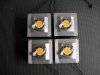
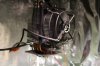
I didn't attach the wrong pictures, I just wanted to illustrate that I had working DIY's. It occurred to me that neither picture was particularly useful to illustrate the discussion at hand, but I didn't take any super-closeup shots during construction. I took a picture just now. Hopefully I didn't burn out the camera's sensor.
The Ideal installation .pdf makes no mention of having to drill holes for the dimples to key into.
http://www.idealindustries.com/media/pdfs/products/instructions/ND_7868-6_50-21_Instructions.pdf
If you think about it, Ideal would want to go to market with a holder that is as easy and fool-proof as possible. It doesn't make sense that Ideal would put out a holder that required their customers to machine little divots in their heatsinks. Every extra step costs money. They didn't build these holders for the home hobbyist, they built them for industrial customers.
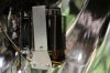
To each their own, but I feel very strongly about this. Don't grind the dimples off! I guarantee you that the two white plastic wings will push down on the COB.
Speaking of which, I was wrong about the two little plastic wings not touching the sink. When I wrote that last night I was looking at an Ideal holder setting loose on top of a heatsink. When they're tightened down, the Ideal holders contact the heatsink at 4 points - those two tiny white nubs on the underside of the wire holders, and at the dimples. The two arms extending inward from the wire holders are the only parts that push down on the COB. Somewhere in their literature it says something about no metal contact with the COB itself, so that makes perfect sense.