Another Cree CXA3070 DIY Thread
- Thread starter captainmorgan
- Start date
medicinehuman
Well-Known Member
It is all looking just wonderful Cap. I just got done ordering all my stuff, the last thing was the 3070 Z4's. Can't wait to see it in action.
Mellodrama
Well-Known Member
I emailed Ideal this morning. Surprisingly, someone wrote back. Here's what I wrote:
"Good morning!
I'm not an industrial customer or anything like that. Just an LED hobbyist.
I was talking with another hobbyist on a forum about how to install the 50-2234C Cree CXA30 COB holder. There are two little dimples on the outer circumference of the holder. He felt that Ideal made those dimples to key into holes on the heatsink surface. He ground the dimples off so that the holder would set closer to the heatsink.
I told him that was a mistake. I believe the dimples act as insurance against crushing the COB with the holder, and also to avoid direct contact between the metal holder frame and the COB. My understanding, after assembling a few of the COB holders onto CPU heatsinks, is that the Ideal COB holder should touch the heatsink surface at 4 points.
Contact should be at the two dimples, and the two little plastic nubs sticking out from underneath the white plastic wire receptacles.
Do you have a moment to tell me whether I'm correct or not? There are people following his forum thread and I don't want other hobbyists to grind off the dimples on their holders!"
Here's what he wrote back:
Hello (deleted),
Thank you for your interest in our Chip-Lok products. Yes, you are correct, the dimples are important and need to make contact to avoid adding too much downward pressure on the COB. The plastic nubs actually help position the contacts, so all four must contact the heat sink. The design of the product is such that we provide the maximum pressure onto the COB which makes the contact to the heat sink, it is not important for the metal holder to make the contact to the heat sink. Our design actually acts as a secondary heat sink pulling 5-10 degrees of heat off of the top of the COB.
Regards,
Barry Reynolds
Engineered Solutions OEM Sales Specialist
IDEAL INDUSTRIES, INC.
1375 Park Avenue
Sycamore IL 60178
Phone: 800-435-0705, Ext. 271
Direct: 815-895-1271
Fax: 888-222-6140
Cell: 815-751-0977
www.idealindustries.com/products/oem/
So, I'm not going to argue with anyone about this. The holders are designed to touch the heatsink at the dimples, and the two little white plastic nubs, just like I said before. Those of you who are determined to do it differently, knock yourselves out. I was going to say that the heatsinks cap'n used are wrong for the Ideal holders, but it looks to me like if you were careful to drill the holes so that the white plastic wire receptacles were lined up with the diagonal axis they would just barely fit.
to bondoman - If I knew how to make a video and post it online I'd do it. It's virtually impossible to explain it in a forum. As previously stated, and confirmed by Mr. Reynolds, the holder is supposed to contact the heatsink at four points. Those 4 points are spread out equally, like four corners of a square. The holder is only supposed to bear down on the COB at two points. See the white plastic fingers that reach in from the perimeter of the holder? Those two plastic fingers have wire inside, and little metal contacts at the tips. When it's all put together correctly, those fingers push down on the COB's two electrical contact patches. The two fingers are all that's pushing the COB against the heatsink. There may be a tiny amount of contact in the corners, where the COB fits into the little recesses that are designed to hold the COB during assembly, but the lion's share of the work is done by the fingers. I used the term "wire receptacles" earlier - the fingers are the same thing.
Try as I might, I know that a verbal explanation is insufficient. You just have to see it in person to understand. And in case you think I'm off my rocker, I've built dozens of PC's. I know that the heat-producing gizmo (CPU or COB) has to make good contact with the sink or heat transfer is severely compromised.
I don't wish to make cap'n feel bad or anything. I don't have a need to prove I'm right. I just want people who are spending their money and time based on advice gleaned from these forums to have the best information available.
Last edited:
Mohican
Well-Known Member
@deleted (jk) That is so cool that they responded so quickly. Sounds like they need to update their documentation.
@captainmorgan - So with the dimples removed does the holder sit flush or does the COB hold it away from the sink?
@captainmorgan - So with the dimples removed does the holder sit flush or does the COB hold it away from the sink?
captainmorgan
Well-Known Member
Good info Mell,wish these companies would put a little more effort into their documentation. I think these should work fine as is but I'll know for the next batch. If you look closely at the close ups I last posted I didn't tighten them enough to make the outer edge touch the heatsink,there is a small gap.
Mellodrama
Well-Known Member
I agree, cap'n, Ideal should put out a little effort and update the video library when they come out with new designs. If they'd provided a clear video of how they want the 50-2234C installed there'd be less mystery. I also agree that you'll probably be OK since you're not cranking the screws down too hard.
Since it sounds like others already have ordered or will order those same heatsinks, can you verify what happens when the Ideal holder is twisted about 30 degrees from where you mounted them so that the plastic wire receptacles are lined up with the diagonal axis? It looks to me like the little white nubs underneath might make contact with the flat plane of the sink surface if the holder is placed just right but it'd be great to have you confirm.
I was thinking about buying some of those sinks myself. But I couldn't tell if the holder would set inside the perimeter of the base so I didn't order any.
medicinehuman
Well-Known Member
I swear I learn something new every day. Very interesting and informative, I will try to use it to my advantage. Thanks much.
it's ok, I'll take your word for it. It's just hard to see in that picture, it looks like an air gap between the cob and heatsink, but what you're describing I'm sure that's not the case.I emailed Ideal this morning. Surprisingly, someone wrote back. Here's what I wrote:
to bondoman - If I knew how to make a video and post it online I'd do it. It's virtually impossible to explain it in a forum. As previously stated, and confirmed by Mr. Reynolds, the holder is supposed to contact the heatsink at four points. Those 4 points are spread out equally, like four corners of a square.
captainmorgan
Well-Known Member
I've got $344 in the major components for 4 of them which is the COB's,CPU coolers,drivers,COB holders and fan power supply.How much have the parts cost so far Rasta Homer?
When you add in all the little things,power cords,wire,connectors,fuses,screws,thermal paste,shrink tube,drill bit and tap it should still cost less than $100 each.
The plastic nub is right at the edge of the heatsink so it would only take maybe a 5 degree counter clockwise rotation of the screw holes to make all four contact points.can you verify what happens when the Ideal holder is twisted about 30 degrees from where you mounted them so that the plastic wire receptacles are lined up with the diagonal axis?
captainmorgan
Well-Known Member
I've definitely seen worse but mine were not flat and took a fair amount of elbow grease to flatten. I wasn't going risk fairly flat on a ceramic COB.How far off of flat were your Alpine 11s when you started sanding? Mine were fairly flat compared to the dell e310 heatsink I used on my first cob cooler which was so far off from flat it took a lot of sanding.
captainmorgan
Well-Known Member
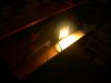
Well I finally had time to do some wiring and fired up one of these COB's and I have to say,WOW they really put out some light.


captainmorgan
Well-Known Member
This thing blinds me and the camera,I can't even look at it with my grow room glasses on.
Attachments
-
 789.4 KB Views: 290
Mellodrama
Well-Known Member
I know, it looked like an air gap to me too, and I was standing right there looking at it. I think these things are so bright that some light bounces back thru the ceramic housing. The COB is definitely pressed down against the heat sink.It looks like an air gap between the cob and heatsink, but what you're describing I'm sure that's not the case.
Mellodrama
Well-Known Member
Oh, hey, I wrote back to the guy at Ideal about using heatsinks that don't support the little plastic nubs underneath the white plastic "fingers". What he wrote won't make much sense to people who don't have a holder to play with. I set a holder on the counter and pushed down at the screw holes. With a small amount of pressure applied, the holder flexes so that the nubs make contact. I don't necessarily understand the "big picture" but I'm sure what I saw has something to do with what he wrote...
"Yes, the white nubs actually put upward pressure on the connector which puts downward force for the contact to COB. They might want to be careful that they are not using too small of a heat sink though I do not know their application. Yes you may use my info on the forum."
Regards,
Barry Reynolds
Engineered Solutions OEM Sales Specialist
IDEAL INDUSTRIES, INC.
1375 Park Avenue
Sycamore IL 60178
Phone: 800-435-0705, Ext. 271
Direct: 815-895-1271
Fax: 888-222-6140
Cell: 815-751-0977
www.idealindustries.com/products/oem/
overthinkingismything
Member
This is how I understood they functioned when I ordered mine. good to have confirmation from ideal.
As the holder is tightened downward the white nubs are forced upward from the heatsink surface, and higher relative to the holders frame. This nub (which is pressed against the heatsink) and the contact point (which connects the solder pads on the COBs) are parallel to each other and connected by a perpendicular beam. This, in effect, acts as a lever/fulcrum maintaining pressure on the COB at the solder pads as the holder is tightened down.
This holder does not need any modification to function as intended on a flat plane.
With that being said, some modification may be necessary depending on the project (like for instance dremelling out a portion if you want to use the thermocouple point.
Oh, hey, I wrote back to the guy at Ideal about using heatsinks that don't support the little plastic nubs underneath the white plastic "fingers". What he wrote won't make much sense to people who don't have a holder to play with. I set a holder on the counter and pushed down at the screw holes. With a small amount of pressure applied, the holder flexes so that the nubs make contact. I don't necessarily understand the "big picture" but I'm sure what I saw has something to do with what he wrote...
"Yes, the white nubs actually put upward pressure on the connector which puts downward force for the contact to COB. They might want to be careful that they are not using too small of a heat sink though I do not know their application. Yes you may use my info on the forum."
Regards,
Barry Reynolds
Engineered Solutions OEM Sales Specialist
IDEAL INDUSTRIES, INC.
1375 Park Avenue
Sycamore IL 60178
Phone: 800-435-0705, Ext. 271
Direct: 815-895-1271
Fax: 888-222-6140
Cell: 815-751-0977
www.idealindustries.com/products/oem/
captainmorgan
Well-Known Member
I finally had time to finish wiring things up.