SoMe_EfFin_MasS_HoLe
Well-Known Member
Thanks. If I wanted a longer distance on the wire to mount the driver external to the tent, would I be safe going with a smaller gauge (thicker) wire?
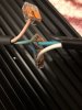
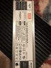
Yes, I dont see a problem with that. I'm not sure what gauge was used but a few people have done that. Though the heat from hlg drivers are minimal. If I remember correctly, the clips that are next to the solder points on the board are compatible with 14 ~ 18 gauge wire. I could be wrong but I'm 99.98% sure of it. Also, if you're going to run the wires through the tap holes on the sink. You might want to look into adding some wire shrink wrap. (I like double walled) My wires dont move much. I have noticed that if you're not gentle when they are put through the tap hole. They will fray a bit. You definitely dont want that to happen. Nothing says electric shock or possible fire than frayed wires. I've tried several size rubber groumets in said tap holes but nothing would fit. I mean it's not as if I pull on the wires but it is nice to know if an accident happens then your output wires are protected. Plus it would make it look much cleaner. (I'm a sucker for aesthetic') I asked @Stephenj37826 a few months back for the inner diameter of said tap holes. He must have missed the post. It would be nice to know but it's not a problem. They are super busy but their customer service is top notch. I've not had any issues but the ones who have were promptly taken care of. Hope that helps. If you have anymore questions and I know the answers I'm happy to help. If not then I could help you figure it out so we both can learn something new.

 .. but that one board that did work was insanely bright I can’t imagine both.


