Al Yamoni
Well-Known Member
Nothing still..I would connect positive (red) lead from DMM to positive wire at driver then connect negative (black) lead from DMM to first COB's positive connection and try again.
Nothing still..I would connect positive (red) lead from DMM to positive wire at driver then connect negative (black) lead from DMM to first COB's positive connection and try again.
Yes sorry DMM = Digital Multimeter.I can't get the lights to turn on or the meter to read with the meter inline.. I assume that DMM = Multimeter?
It will have either a glass fuse or in higher grade DMMs HRC ceramic (white) fuse.
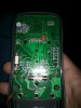
Not the one on the left its the one in the middle at the bottom. You see that jumper wire looking thing under the white fuse? That's the current shunt, the current is measured acrossed this shunt. Remove that fuse and use the DMM to test continuity by putting the red prove back into the voltage port and touching one probe to each side and listen for an audible beep.Is the fuse the white cylinder on the left?View attachment 3509445
Set to ohms and touched each end of the fuse and get no resistanceSorry forget using continuity doesn't look like your meter has it. Flip it to ohms setting and test resistance across the fuse and report back.
It goes from displaying 1 then I touch it with the meter and it displays 0.00No resistance as in the meter displays OL?
If you touch the probes of the DMM together what do you read? Sounds like the fuse is OK cause you should get an infinite reading OL or 1 on some meters when fuse is brokenIt goes from displaying 1 then I touch it with the meter and it displays 0.00
I have it on the 20k Ohm setting and the DMM displays a 1. touch the leads together and the the DMM says 0.00If you touch the probes of the DMM together what do you read? Sounds like the fuse is OK cause you should get an infinite reading OL or 1 on some meters when fuse is broken
Isn't the 10A fuse soldered? It looks like someone was already in there.
It is soldered in place. I'm not sure what you mean by the connection on the right looking dark?After having a second look at the picture you posted. The fuse looks soldered in place as previous poster stated. The connection on the right to the board looks pretty dark in the picture. How does that connection look in person?
it looks like a solid connection to me. the photo does look a lot worse than the actual board.You are touching red probe to one side of fuse and black probe to opposite side of fuse correct? What I mean by the connection. The wire that comes off the right end of the fuse and goes to the circuit board. It just looks dark like someone played around in there before to replace fuse or something.