Getgrowingson
Well-Known Member
Usually you only move positive lead or negative lead. Not both
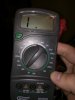
I agree sounds weird, It shouldnt matter which probe is touched on what side of the fuse the readings should be the same. One result states the fuse is blown but the other result states its ok lol If fuse is good you should get close to the same reading as when you just touch the two probes together.Sound weird. Put the meter on the ohm setting put the leads together. You should get ~0. Put one lead on one end of the fuse and the other lead on the other end. Should be close to 0 as well. When the leads are sitting in free air not touching anything or each other it should say OL or infinite. We're just trying to find out if your fuse will conduct electricity or not. If it's less then 5 ohms your fine.
Negative lead always stays in the COM (Negative) port and only the red probe must be moved and only for 10A range in this caseUsually you only move positive lead or negative lead. Not both
No beepThe diode setting at the bottom which is highlighted in red between the 200ohm and 10A setting, If you switch it to this setting and touch the probes together does the meter beep?
ok cause if we had a continuity mode this would be much easier lol. Either way I think there may be issues with the DMM considering you get different readings when making the same measurement just by switching the probes from side to side on the fuse which isnt right they should both read the same IMONo beep
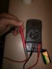
Correct. Black-com red-VmAYep selector switch is in good position and your are installing probes into COM and VmA ports correct?
Thank you. I'll be chugging along trying to figure this out.I'm with Canadian one on this one. Would borrow someone else's meter and try it that way. That one seems a little sketchy to me and wouldn't trust any amount of current flowing through it. Seems as though your having driver issues imo. As long as your dim wires are floating and your within your Voltage limits you should have the max output current and it seems as though it's either limiting current for some reason or its just a faulty driver. There's always a chance one out of a thousand could be screwed. If you plan on building another light in the future in would buy another driver and try it out. If it works keep the new driver and send the other back on warranty. Then when you get your replacement build your new light with it. Either that or get another meter and see what the output current is. But even then it will only be showing you that it's lower then it should be. All signs in my eyes point to faulty driver. I would also check the resistance of the entire circuit and compare it to the sum of all the resistances of each cob. They should be very similar. If not you have a bad connection somewhere. When you check your connections ensure the positive of the cob is on the positive of the holder just to double check. I'll think about it some more over some sleep and come with more suggestions tomorrow. Good luck bro
Just picked one up. I'll open the package here in a second. It had better work.Sorry Al had to step out again. Beautiful eclipse out here in the northeast. Holy shit wtf has happened?
Anyway you should not plug anything else into your circuit until you test the integrity of your circuit and each COB. This is to remove any variables in your design. I can show you how to do this using the way I test my circuits before powering any drivers but we need a few things straight.
Do you have a working multimeter?
I have a blurple light that I plugged into the killawatt and got accurate readings so whatever it tells me about my diy light I'd be inclined to believe.I'll vote for a faulty driver based on the 45VAC Killawatt reading--was that confirmed?
wow that is only 10-70mA something drastic going on there. I would have to think faulty driver. DIm circuit is connected to pin 1 & 2 on potentiometer? If you have the other driver handy I would plug that one in and that will verify you dont have an issue in your LED array and its in fact in the other driver.when powered on with the DMM in the series on the 10A mode it reads 0.07 with the pot all the way up and with the pot all the way down it reads 0.01