Thermometers, Thermocouples, and Thermal Readings

AquariusPanta

Well-Known Member
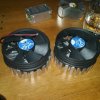
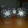
What's up fellow RIUians. I wanted to make a thread on thermal readings, as I haven't seen hardly anyone document thermal readings for their cob units, whether through commercial or DIY and I find it to be very important for us who want our lights operating at optimal temperatures. From what I can gather, it's uncharted territory for a bunch of us here and hardly anyone has yet attempted to fully enlighten others regarding this kind of procedure; I'm here to do just that with this video:


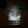
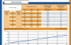
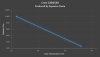
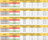
Here are some readings I recorded recently:

Thermal Readings.png

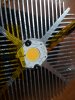
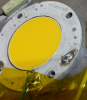
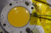
As you can probably tell, there's an obvious anomaly with the sample #1 for the Vero 29, as it gets progressively hotter throughout the testing period. While testing, I held up my Apogee PAR meter underneath both samples at equal distances and positions and read similar outputs, so I knew then and there that something had become loose and that the thermocouple had been absorbing blank-range heat from the LES.

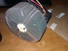
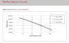
Also important to point out is that the Vero 29 runs a little more aggressively than it's Cree counterpart, thus explaining a little on why the CXB3590 runs cooler. Throw in the math that it also has a higher efficiency range than the Vero 29, there's no question on why the CXB3590 runs as cool as it did in these testings. All samples were ran with 120mm fans at 5V.

Anyways, I'd like to see other's attempts at recording and sharing their own thermal data, so please feel free to share any data that you have and remember that the more variables listed, such as ambient temperature, the better the rest of us will make of that input.

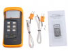
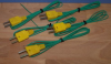
Here's a link to the digital thermometer from the video:
http://www.ebay.com/itm/400542887700?_trksid=p2060353.m2749.l2649&ssPageName=STRK%3AMEBIDX%3AIT
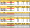
 

AquariusPanta

Well-Known Member
Yes, the K-type thermocouple came along with Digital Thermometer.

Attached is the Case Temperature vs. Relative flux for the Vero:

upload_2016-1-18_15-30-46.png

Cree doesn't offer such a graph for its CXB3590, so I went ahead and created my own. It's not as curvy as the Vero version but is still reliable for reference:

upload_2016-1-18_15-35-51.png

Also, I did some back tracking recently and realized the temperature values for the excel sheet didn't match up with what I had written down in my notebook (so many notes, not enough attention XD). Here is the correct excel sheet:

upload_2016-1-18_15-43-27.png

The only difference is in Test #4.

As you can tell by the temperature graphs, Case temperature plays a role in how well our cobs are performing.

Here's a video from Bridgelux briefly describing how they apply their thermocouples:


Attachments

Abiqua

Well-Known Member
I have been using a range for my Ta, or a weighted mean and not just an average, so I can at least tell the margin of error....

I prefer this because we know that Ta is never static and thermal design should always take that into account and in most cases Ta is a direct result of the growroom itself and is your growroom always a static temp?

What are methods @AquariusPanta ? is it a significantly different mindset ....I get the starting point for a static Ta, but in reality do you think we need a little more input for long term thermal design?

:peace:
 

AquariusPanta

Well-Known Member
@Abiqua

That is a great question to bring up. I performed a few tests in between the others that I posted, where the 4' x 4' tent was sealed and with no ventilation besides a few 4"-6" diameter openings. This showed inside tent temperatures rising upwards to 95 F, thus concluding that if one were to run a similar light setup, say for flowering, that they would need to introduce a method of heat/air ventilation in order to properly provide enough light output and at the same time, prevent tent temperatures from being too intense by bringing in colder air from the neighboring Ta.

As far as long term thermal design goes, I believe it's a huge factor that plays into our lighting setups and grow rooms. I don't think I mentioned it before but the tests that I ran all proceeded with +2 hours of operation before readings were taken, with some lasting upwards of up to ~6 hours. It would be difficult to disprove that ambient temperature (Ta) is affected by our lights and thus the Ta is always changing but important to keep in mind is that the ambient temperature isn't dependent on our lights, with various factors playing into how cool or warm a room is. For most indoor growers, indoor temperatures range from 68 F to 84 F, as many grow within their own homes and are thus posed to run AC in the summer and heat in the winter in order to offset the weather outdoors.

If I misinterpreted your question(s) or notion of inquiry, please feel free to ask from a different angle, as this topic makes for a good conversation.
 

robincnn

Well-Known Member
AP you asked how i fit that AWG 29 thermocouple. Here are some photos of a quick test setup i did.
Shows how the thermocouple should not get close to LES. This is not an issue with cxb 3590 as the Tc pint is further away from LES.
I bend the thermocouple to get a spring action so that the thermocouple touches the case.
I do not use thermal adhesive to mount thermocouple. Kapton tape works fine.


upload_2016-1-21_9-26-46.png
upload_2016-1-21_9-27-28.png
upload_2016-1-21_9-28-1.png


The 2 channel K type from ebay work fine for me however its thick thermocouple leads were not good.
I prefer this.
www.ebay.com/itm/K-Type-Thermocouple-Wire-for-Digital-Thermometer-Temperature-Sensor-Probe-TC1-5p
upload_2016-1-21_9-29-26.pngupload_2016-1-21_9-30-4.png


Here is some data I have for 80-85 watts with large heatsink and powerful 120mm fan

Vero 29 2.15 amps, No optics
COB 1 Tc = 44.5C, COB 2 Tc= 47.2C

CXB 3590 2.35amps
COB 1 Tc = 36C, COB 2 Tc= 38C

You cannot say that Vero runs hotter than CXB with the above data.
I think it is fine to compare Tj of different COBS. However Tc of 2 different COBS should not be compared. The Thermal resistance between Case and the junction is different for different cobs. Also the Tc point location is different.

Rj-c of Vero is available but not available for CXB. I think CXB has higher Rj-c than Vero
upload_2016-1-21_9-49-41.png

From SDS post Tj= Tc + ( Rθj-c * Vf *If * ( 1-eff ) )
 
Last edited:

AquariusPanta

Well-Known Member
AP you asked how i fit that AWG 29 thermocouple. Here are some photos of a quick test setup i did.
Shows how the thermocouple should not get close to LES. This is not an issue with cxb 3590 as the Tc pint is further away from LES.
I bend the thermocouple to get a spring action so that the thermocouple touches the case.
I do not use thermal adhesive to mount thermocouple. Kapton tape works fine.


View attachment 3590380
View attachment 3590381
View attachment 3590382


The 2 channel K type from ebay work fine for me however its thick thermocouple leads were not good.
I prefer this.
www.ebay.com/itm/K-Type-Thermocouple-Wire-for-Digital-Thermometer-Temperature-Sensor-Probe-TC1-5p
View attachment 3590383View attachment 3590384


Here is some data I have for 80-85 watts with large heatsink and powerful 120mm fan

Vero 29 2.15 amps, No optics
COB 1 Tc = 44.5C, COB 2 Tc= 47.2C

CXB 3590 2.35amps
COB 1 Tc = 36C, COB 2 Tc= 38C

You cannot say that Vero runs hotter than CXB with the above data.
I think it is fine to compare Tj of different COBS. However Tc of 2 different COBS should not be compared. The Thermal resistance between Case and the junction is different for different cobs. Also the Tc point location is different.

Rj-c of Vero is available but not available for CXB. I think CXB has higher Rj-c than Vero
View attachment 3590388

From SDS post Tj= Tc + ( Rθj-c * Vf *If * ( 1-eff ) )
Nice, it would appear that the thermocouple you went with closely resembles the one that Bridgelux used in respect to gauge. There's like little to no way of applying the stock thermocouple that comes with the digital thermometer I mentioned in the same application that you provided regarding the ledil clamp, as it's just too thick of a gauge to fit in and the tape wouldn't be enough to properly hold together the targeted mating surfaces.

On a reasonable level, I agree with you that we probably shouldn't compare the Vero 29 and CXB3590 case temperatures based on various factors such as Tc measuring point but I do think we can make a few conclusions based on this data. One of those conclusions would be that if the thermocouple was properly applied to the Tc measuring point of the Vero 29, that the Vero 29 can't be any hotter than what the readings were, as we're led to believe that the Vero 29 assumes a higher Tc reading due to the minor distance between LES and Tc measuring point. How much of an offset occurs from the neighboring LES and through the thermocouple, I'd like to know, as we then could approximate what the Tc of the Vero 29 would be with a given reading.

One of the main reasons behind my testing was to determine how much cooler one cob operated in comparison to another at similar currents, with the understanding that one would be dissipating more than the other at similar currents. I already knew there were factors, based on data and calculations, that one would operate at cooler temperatures but had the drive to test both anyways. If the mention of doubt was brought to Bridgelux regarding the Tc measuring point of the Vero 29 and it was confirmed as being reliable, then one could easily conclude that one operates cooler than the other. Again, obviously they have different thermal properties, such as the material they are made of, but that's besides the point. The point is to conclude on how they operate in real life conditions and to compare it with calculations that are made with the use of data that we are provided through Bridgelux and Cree.
 

kony brado

Well-Known Member
AP you asked how i fit that AWG 29 thermocouple. Here are some photos of a quick test setup i did.
Shows how the thermocouple should not get close to LES. This is not an issue with cxb 3590 as the Tc pint is further away from LES.
I bend the thermocouple to get a spring action so that the thermocouple touches the case.
I do not use thermal adhesive to mount thermocouple. Kapton tape works fine.


View attachment 3590380
View attachment 3590381
View attachment 3590382


The 2 channel K type from ebay work fine for me however its thick thermocouple leads were not good.
I prefer this.
www.ebay.com/itm/K-Type-Thermocouple-Wire-for-Digital-Thermometer-Temperature-Sensor-Probe-TC1-5p
View attachment 3590383View attachment 3590384


Here is some data I have for 80-85 watts with large heatsink and powerful 120mm fan

Vero 29 2.15 amps, No optics
COB 1 Tc = 44.5C, COB 2 Tc= 47.2C

CXB 3590 2.35amps
COB 1 Tc = 36C, COB 2 Tc= 38C

You cannot say that Vero runs hotter than CXB with the above data.
I think it is fine to compare Tj of different COBS. However Tc of 2 different COBS should not be compared. The Thermal resistance between Case and the junction is different for different cobs. Also the Tc point location is different.

Rj-c of Vero is available but not available for CXB. I think CXB has higher Rj-c than Vero
View attachment 3590388

From SDS post Tj= Tc + ( Rθj-c * Vf *If * ( 1-eff ) )
hi robin,or A.P
If it's not a big trouble ,can u show a picture or the 3590s measuring point,i didn't get where exactly is it.
thanks allot

edit:oops,sorry i find it,i didn't notice as it's so small :wall:
 
Last edited:

Abiqua

Well-Known Member
I really wanted to post something a lot sooner, sorry gang, slipped a disk recently while wrestling timber tigers and haven't been able to walk for two weeks. Fun. :joint:

There are three things that stand out to me....all are almost never accounted for in "simple" thermal design and some may have benign effects, others may not.....

- Ideal blackbody
......[we as a group seem to mostly are work with "grey" bodies and what about Cu? :)
- Point Source vs Radiated Source
this one seem the most important as I have seen suggestions to increase Heatsink Rh [resistance] up to 33% in some cases to allow for this...
- Horizontal Mounting vs. Vertical mounting
in most thermal design calcs, it is assumed a vertical mounting, this is why we have long fins on extruded heatsinks, the original purpose was for vert placement @ttystikk :)
...most mount horizontal I assume, not a huge deal, again, more resistance helps to not be noticeable.


This is good too, both parts!

http://www.heatsinkcalculator.com/blog/estimating-forced-convection-cooled-heat-sink-performance-in-a-ventilated-enclosure-part-1/#more-162

http://www.heatsinkcalculator.com/blog/estimating-forced-convection-cooled-heat-sink-performance-in-a-ventilated-enclosure-part-2/
 

Abiqua

Well-Known Member
Fucking rollitup and I can't removed the line thru script, thanks RIU and Win10...


Here's some of my own math...wish I had time for fancy charts @AquariusPanta

Vero 10
10w radial Heatsink Ebay
graftech graphite TIM
Meanwell APC 350 driver
Max 6685 thermocouple chip / Arduino UNOr3
active cooling 5v thermaltake 2.5" fan [65mm]

heres mye Mathe
measurements taken after about an hour, then read for 4-5....Tc is average for 1 minute over all 4 hours thru datalogging....


Tj 40.175
rj-c 1.49 c/w [vero10@350mA] [another guess because Rj-c, isn't technicallygiven!]
Tc 35.5
Rb .59 c/w
Tb 33.3 C
Rh 2.94 c/w
33.3 - 23/3.5 = 2.94 C/w


Tj = Rj-a xPd or.....
Tc= Tj - [Rj-c x Pd]


Tb =
Tc - [Rb x Pd]


Rh = [tb-Ta]/ PD


20151105_215443 - Copy.jpg

20151105_215558 - Copy.jpg

20151105_225209 - Copy.jpg

20151110_175907 - Copy.jpg
 

Abiqua

Well-Known Member
Last edited:

AquariusPanta

Well-Known Member
Although a lengthy endeavor it may prove, it would be ultimately beneficial to all for any individuals to establish credible data entailing which heat sink and fan combos work best for our favorite cobs in different configurations and at various outputs with temperature readings from our digital thermometers/thermocouples.
 

Abiqua

Well-Known Member
Although a lengthy endeavor it may prove, it would be ultimately beneficial to all for any individuals to establish credible data entailing which heat sink and fan combos work best for our favorite cobs in different configurations and at various outputs with temperature readings from our digital thermometers/thermocouples.
I am switching over to IR temp I believe....I have a paper, suggesting that thermocouples might have an Error margin up to 58% + - ! ouch! computer modeling was coming out more accurately in many of their scenarios, .......:joint:

EMI interference coupled with radiometric interference seems to be the biggests problem areas.....
 
Top