my uncle is a master plumber, with no work so he also has free time. if i get stuck or i dont feel comforable ill make him help me, and my skills arent to bad either.
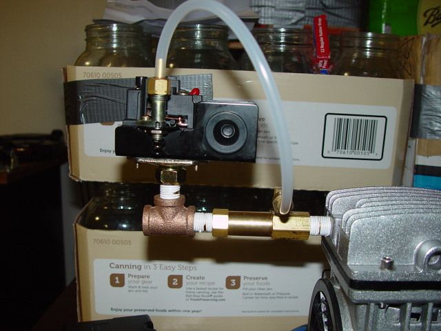
i just found a pressure switch that has a 55psi differential and a unloader valve, i think that will satisfy me.
http://www.ebay.com/itm/PRESSURE-SW...501?pt=BI_Air_Compressors&hash=item2c626ac155
i just found a pressure switch that has a 55psi differential and a unloader valve, i think that will satisfy me.
http://www.ebay.com/itm/PRESSURE-SW...501?pt=BI_Air_Compressors&hash=item2c626ac155