Beehive
Well-Known Member
Nice. This is what I did to mine. I threw a piece of shrink wrap tubing over my splicing job.
View attachment 4781455
Where'd you get the knob for the dimmer switch? Is there a internal size?
Nice. This is what I did to mine. I threw a piece of shrink wrap tubing over my splicing job.
View attachment 4781455
HLG sent me the knob with my kit.Where'd you get the knob for the dimmer switch? Is there a internal size?
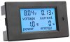
Not if you're measuring (outputing) more than 100V or 20A DC. 20A DC is doubtfull, haha.Will this work to monitor the driver? I want to build a box with a read out.
Amazon- "DC Power Monitor, DROK Digital Multimeter DC 6.5-100V 20A Voltage Amperage Power Energy Meter, Volt Amp Tester Gauge LCD Digital Display with Built-in Shunt"
I realize you probably know most of what I'm going to say, but others might not, so please don't take offense.
...
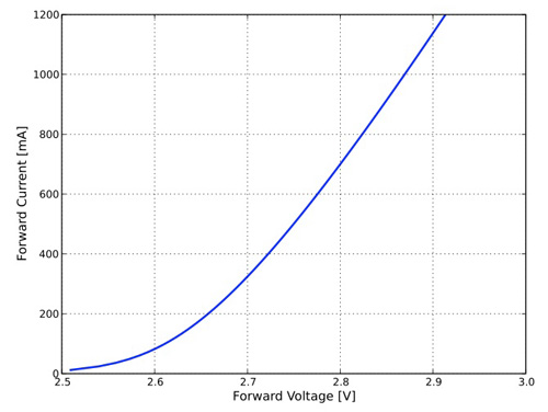
On the hlg-240h-c1750, when you adjust the driver to 1750mA, you are in effect telling the driver to adjust the voltage to whatever level it needs to be at, so as to maintain an output current of 1750mA. If you look at the forward voltage vs current graph that @pop22 linked, you'll see that at 1750mA, the QB132 board will be at approximately 35v. So, if the driver is set at 1750mA and you have 3 QB132s hooked up in series, the driver output will be 105v @ 1750mA. If 4 QB132s are hooked up, then the driver will output 140v @ 1750mA.
It's confusing when you say this "On the hlg-240h-c1750, when you adjust the driver to 1750mA...", right after saying "In a constant current driver, the current is held constant, but the voltage is allowed to float to whatever level it needs to be at, to maintain that constant current."
Say you have a hlg-320h-c2100b driver with a potentiometer set to output 700mA, but you have determined that you need 1750mA, so you adjust the potentiometer. As the resistance from the pot increases, the driver senses the increase and responds by increasing the voltage to the boards. (It does this whether it's a CC driver or CV driver. Why? Because the current through an LED is determined by the amount of forward voltage to the LED. So, if you want more current, you need to increase the voltage.) The increased voltage from the driver causes the LEDs to allow more current to flow, causing the driver to output more current.
When you start out at 700mA, the voltage to the boards is about 33.3v/board (133.2v total) for an output of 23.3W/board. When the potentiometer resistance has increased enough that the driver is outputting 34v/board, the current will be 1050mA for 35.7W/board. Keep going to 34.5v/board and your at 1400mA for 48.3W/board. When you finally get to 1750mA you'll be at 35v/board for 61.25W/board. I got these numbers from the forward voltage vs current chart on HLGs site.
Earlier I said, that the driver changes the voltage to the boards, to change the current. That makes sense for a CV driver, because the pot directly controls the voltage. Increase the pot on a CV driver to output 34v and the boards will consume 1050mA each. Increase the pot on a CC driver to 1050mA, and what happens? The driver increases the voltage to the boards until it senses that the boards are drawing the correct current level, which for 1050mA happens at 34v/board.
It doesn't matter if we set the CV driver to 34v or the CC driver to 1050mA, we end up with 1050mA/board and 34v/board for 35.7W/board. For this example, we'll assume we have a set of knockoff boards connected to an hlg-320h-36b set to 34v. Since these are knockoffs, all of a sudden 10 LEDs in one of boards shorts. While your busy swearing, the driver continues to output 34v, but the remaining LEDs will get a bigger share of the 34v, causing the current to increase. This condition could lead to thermal runaway, among other things, but regardless, the driver is now using more than 35.7W/board.
If the knockoffs were connected to an hlg-320h-c2100b set to 1050mA, and the LEDs shorted, once again the remaining LEDs will initially get a bigger share of the 34v, causing the board to call for more current from the driver, but since this is a CC driver, instead of allowing the current to increase, the driver reduces the voltage to the boards to keep the current at 1050mA. So, it's using less than 35.7W/board.
So, basically, the qb132 doesn't "need" 36v, it varies with current, etc. etc. And that 1volt under (143v) on the 240h-c1750 doesn't matter, is what I'm hearing. Ok.
I know about fV and I've seen the graph. Whenever I try and apply the little I know and formulate a reasonably simple question...things gets confused. I thought forward voltage was defined as the minimum amount of voltage required the power/light the light. Guess not. Or not without some asterisk.
Forward voltage can be used two ways. The way you described, and to describe a voltage applied to a diode, so that the anode is more positive that the cathode. As opposed to reverse voltage, which is the opposite condition. If the board is hooked up to the drivers leads correctly, then the LEDs will be forward biased, and hence have a forward voltage when power is supplied.
The qb132 looks like it's fV is just under 33.5v based of that graph... The flux chart goes from 32.7v to 34v.; it doesn't even show 36v on that particular page/chart, hah.
The info above says "QB132 are 36V and can be used with standard drivers...". So...is 36v the max then? "Allow tolerance of an additional 1V while matching drivers." An additional 1v allowed to the ratings in the flux characteristics chart below? Or to whatever voltage rating (cc range) a potentially paired driver can provide? (not expecting answers, just pointing out questions).
The graphs don't necessarily show the whole range. I imagine the graph on HLGs site just shows the more common settings. Their site says the QB132s are 36v, 2100 mA max, (36v x 2.1A = 75.6W) which jibes with the 75W/board. So, yeah, I'd say 36v I'd the "official" max.
35v x1750ma x 4 boards = 245Watts, which is about the max wattage of the hlg-240h-c1750b
I also wanted to point out that if you set the driver to output 1750 mA, it wouldn't matter which driver you were using (the hlg-240h-c1750b, hlg-320h-c1750b, or the hlg-320h-c2100b) all three drivers would be outputting the same 140v @ 1750mA to the 4 QB132s.
The different drivers have different constant current regions and other shit though. Four qb132 may fall outside that range on one of these drivers (asterisk), no? But yea, I see what you're saying about the math producing the same wattage, yup.
Yes, the 240h-1750b might only be able to get 240W of the 245W, but the 240h-1750a would get to 245W, so I included it.
I think you should figure out how many watts you want per sq ft. Then decide what driver you want. If you want 15W/ft², then you'd only need (15W x 30 sq ft = 450 total watts) 225W per driver, so the hlg-240h-c1750 would work. If you want 17.5W/ft², then you'd need 262W per driver, which would eliminate the 240h.
I did. It's a veg area. The area is 3x9 ish, call it 30sq/ft. 15-20w per sq/ft is generally recommended for veg for QBs, right? The boards can run a max of 75w without a heatsink. And the list of suggested drivers basically show that they're trying to power the boards between around 50w - 75w. I want the ability to run up to that 'max' of 70-75w. 30sq/ft x 17.5w (avg) is 525w (so 450-600w).
4 boards in a pack, 4x75w = 300w. 300w / 15 sq/ft = 20w per sq/ft. (this is half the area)
4 boards in a pack, 4x60w = 240w. 240w / 15 sq/ft = 16w per sq/ft. (this is half the
Too bad I can't devote 12 boards to it for simplicity. I might have to go with two 320w drivers then, just to have the power *available*.
Run four qb132s off a 320h-c2100b, and dim it down? Will that actually reduce current output below 2100mA, or is it just sorcery via the 3-in-1 dimming (like applying a resistance or voltage, etc...
Yes, if you dim the pot the driver will lower the current. Unless the driver has an internal flux capacitor, in which case the current will increase until the driver is outputting 1.21GW. lol
Thanks
Response in body.
thank u sir, you just answered a few lingering questions that I had.
ill throw a few more out there that have been troubling me.
the examples you used for dimming i assume are based on a regular 0-10V dimmer which works by applying resistance and adjusting voltage correct? so more voltage means the boards draw more current, and less means they draw less etc.
so my question is when using PWM dimming. since that is actually pulsing the LED to dim it, is it actually winding up sending it less voltage + current in the process? or does that keep those 'constant' and it just changes our perception? or does the PWM control still result in a 0-10V resistance being applied? i dont have any PWM dimmers on my grow lights but I made a table lamp from a cheap strip and got a $5 inline PWM dimmer and been trying to wrap my head around this. am I making sense or am I misunderstanding something here.
also not for HLG boards, but sometimes for strips I see a min/typical/max voltage at different currents. if the lowest they show is nominal, is there an easy way to figure out what running at say 1/2 or 3/4 nominal/test would draw voltage wise if its not shown on the datasheet?
sorry to take the HLG thread slightly off track but thought these questions are relevant to current discussion and maybe to someone trying to do PWM dimming w arduino.
The 3 ways to dim the B type drivers are with a 100k potentiometer, a 1 to 10v DC signal, or a 10v PWM signal. What I think is happening is that there is an IC chip or a microcontroller that is reading the input from the dimmer and converting it to signal to control the driver output. For example, if the resistance of the potentiometer is 64K, then the microcontroller would "sense" that it's at 64% of max and adjust the output accordingly. If the dimming circuit has 6.4vdc applied to it, again, the microcontroller would "sense" that is at 64% of the 10v. If the dimmer had a 10v PWM signal with with a duty cycle of 64%, you guessed it, the microcontroller would "sense" it.
It wouldn't be a good idea to send the output voltage to the boards as a PWM voltage. The constant spikes in current and voltage would be detrimental to the LEDs and the driver, and you would end up with more heat to deal with from both the driver and the boards. That's why I think the dimmer is connected an IC chip or microcontroller, which in turn controls the output of the driver.
also not for HLG boards, but sometimes for strips I see a min/typical/max voltage at different currents. if the lowest they show is nominal, is there an easy way to figure out what running at say 1/2 or 3/4 nominal/test would draw voltage wise if its not shown on the datasheet?
Not that I can think of.
That is how it works. It pulses the current faster than you can see to achieve dimming. Just dialing back current causes color change which is a bummer if you are planning on 3000k, but are really getting 6000It wouldn't be a good idea to send the output voltage to the boards as a PWM voltage.
That is how it works. It pulses the current faster than you can see to achieve dimming. Just dialing back current causes color change which is a bummer if you are planning on 3000k, but are really getting 6000
I think the Mean well driver does pwm dimming regardless of which method you use to tell it to dim. Could be wrong, but it appears that way when my simple mind tries to make sense of their drawings, and poor description.thats what i used to think too but then i was reading something that made me think that a PWM device attached to a MW is just adjusting the voltage or current based on the values provided. i have to dig thru my browser history to find it but that is why I had asked the question in the first place.
but also regarding what you just said, this is from the MW PWM-120 driver description:
"PWM-120 series is a 120W AC/DC LED driver featuring the constant voltage mode with PWM style output,which is able to maintain the color temperature and the brightness homogeneity when driving all kinds of LED strips."
so i think in the case of most MW drivers, @TWest65 is right in that a 10V PWM signal is applied to the DIM circuit which results in the driver adjusting its output. but in the case of the PWM series driver that is outputting an actual PWM signal, i think the above is true? it maintains a constant voltage but pulses the current while somehow maintaining color temp? leds are so cool.
I think the Mean well driver does pwm dimming regardless of which method you use to tell it to dim. Could be wrong, but it appears that way when my simple mind tries to make sense of their drawings, and poor description.
This doesnt just go for the pwm series, but any of them with 3 in 1 dimming
not ashamed to admit i am thoroughly confused, especially when thinking about how i run all my boards/strips soft. when a QB is rated at 3000K is that at its test current (2.8A or whatever)? So if I am running mine all at 1.05A what color have I shifted my boards to? if i then dim my driver how does it change from there?
i also am throwing my bet against the PWM series being the only ones that actually output a PWM signal since that is their main feature vs similar models.
brain exploding rn, someone help us understand...
Kind of wondering the same thing. Plants havent seemed to have suffered any but i guess since they have added the pwm series, there must be a difference compared to other dimmablesSo if I am running mine all at 1.05A what color have I shifted my boards to?
no less confused, but this is pretty interesting.
LED Color Shift Under PWM Dimming
Light-emitting diodes (LED) demand different dimming techniques than the analog methods used for traditional lighting because the correlated color temperature (CCT) of solid-state lighting changes with voltage.www.digikey.com
The 3 ways to dim the B type drivers are with a 100k potentiometer, a 1 to 10v DC signal, or a 10v PWM signal. What I think is happening is that there is an IC chip or a microcontroller that is reading the input from the dimmer and converting it to signal to control the driver output. For example, if the resistance of the potentiometer is 64K, then the microcontroller would "sense" that it's at 64% of max and adjust the output accordingly. If the dimming circuit has 6.4vdc applied to it, again, the microcontroller would "sense" that is at 64% of the 10v. If the dimmer had a 10v PWM signal with with a duty cycle of 64%, you guessed it, the microcontroller would "sense" it.
It wouldn't be a good idea to send the output voltage to the boards as a PWM voltage. The constant spikes in current and voltage would be detrimental to the LEDs and the driver, and you would end up with more heat to deal with from both the driver and the boards. That's why I think the dimmer is connected an IC chip or microcontroller, which in turn controls the output of the driver.
also not for HLG boards, but sometimes for strips I see a min/typical/max voltage at different currents. if the lowest they show is nominal, is there an easy way to figure out what running at say 1/2 or 3/4 nominal/test would draw voltage wise if its not shown on the datasheet?
Not that I can think of.