Anyone here controlling your grow room via PLC?

Infamous Zero

Active Member
On my first grow and I immediately noticed while shopping for grow room supplies that quality timers/ heat controller/ ec and/or ppm and ph controllers are rather expensive if purchased separately.

Which brings me to my question; how many of you are taking care of all these controls with a programmable logic controller?

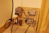
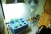
For less than 100 dollars I've built a fully programmable controller for light cycle, water cycle, and cooling ( via a relay operated fan). I don't have a large enough reservoir to attempt ppm/ph control, but it would be completely feesable without too much additional cost.

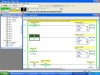
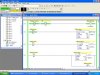
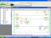
For those of you who are tech savy I'd suggest researching PLC's. The amount of money that can be saved is staggering, and one benefits of such a system includes customization and repeatability, the relays inside this particular controller are rated for over 1 million cycles. And I can fully customize my watering / lighting cycles down to 1 hundredth of a second, however unlikely it is that you would ever need that precision. I have programmed this controller to water less when lights are off, and to refuse operation of the ballast for 10 minutes after the lights have turned off in order to prevent damage to my bulbs caused by hot restarts. I have no fears about leaving this system running unmonitored for several days such as some people who have experienced failure with dial timers.

Just though I would share some information with those of you looking for another alternative to purchasing multiple, and sometimes incredibly expensive timers.

Cheers!
 

Attachments

flamdrags420

Well-Known Member
Would like to hear a bit more about this.
These controllers hook up to your computer? You have software to control them?
 

smoke and coke

Well-Known Member
yes this will work great but it may be a little to high tech for most here to be able to understand the logic programing. but anyone who can understand would be able to make it work.
 

Infamous Zero

Active Member
Yes, I don't want to get anyone confused, you will need to understand computers at a slightly greater level than the general public... however, definitely not to a depth required by "computer programmers"

PLC's use "ladder logic" a rather simple, incredibly easy machine language.

A computer is used to initially program them, and then they can be monitored via your computer, or allowed to run completely stand alone.
 

Cannabox

Well-Known Member
ya, props for setting up a plc , i program, but i i'm not getting that adv with growing ;p nice work.

you using a MH light there? or is that a high watt CFL and hood?
 

Infamous Zero

Active Member
400 Watt MH, its a switchable ballast, at one month it is switched over to HPS.

The resivoir has a float switch, and there is a discrete indicator lamp outside which signals a problem with nute level. A secondary level sensor prevents the pump from burning itself out if the levels get too low and would cause undue wear on the motor.
 

Infamous Zero

Active Member
Following are 3 pictures of ladder logic. And a picture of the controller.

The bare copper wire carries no current, its simply a grounding wire, for safety's sake.

Most of the control wiring is 24V DC, completely harmless to handle

DSC_0253 copy.jpg

Ladderlogic1.jpg

Ladderlogic2.jpg

Ladderlogic3.jpg
 

Infamous Zero

Active Member
any brand names you recommend?

PLC manufacturers banded together a long time ago and came up with a "common" language, while every company has slightly different software, ladder logic is pretty universal.

Usually the hardest part is getting a hold of cheap software. The software is sold separately from the hardware.

... other means can be used to locate software though.
 

flamdrags420

Well-Known Member
good stuff but less than 100 dollars?
I'm sure rockwell would love their paycheck for that software you are using.
An exfactory guy huh? =)
 

Infamous Zero

Active Member
good stuff but less than 100 dollars?
I'm sure rockwell would love their paycheck for that software you are using.
An exfactory guy huh? =)

Actually the software for that particular controller is free. Allen Bradley in an attempt to promote their hardware provided a free version of their software for use with their 10 point controller.

I got the controller for 80 dollars, and the software came right from their website.

I do however have a much larger controller waiting for the right project. That controller is capable of limitless automation. An enormous grow room, with multiple resivoir control, zone based humidity/ temperature control.... you name it and a SLC 5/04 can do it. The software for that controller was obtained through other channels.

If I didn't have access to Allen Bradley, I'd be programming EZ PLC's, or Automation Direct. Both have very affoardable hardware and software.
 

born2killspam

Well-Known Member
I've found that most ppl here balk at the idea of building your own controllers, and would rather spend hundreds of dollars instead of $5-10 and a 1/2 hour painting by numbers with a soldering iron..:(
A few years back I had some nifty home-built circuits made mostly from salvaged parts to control everything except pH since you can't really get around buying probes.. It was a mixed bag, some things were contained on the circuit board, others interfaced with my pc via parallel port in conjuction with X10, I never really attempted to compact anything..
Here are some things you might find useful if you haven't come across them already..
http://damien.douxchamps.net/elec/ph_meter/
http://www.octiva.net/projects/ppm/
 

BloodShot420

Well-Known Member
yo Zero... i just did a search on the site for "PLC" and NOTHING came up... i was about to start a similar thread.. i just started setting all my stuff up with a PLC... I am using an Eaton ELC-PA10AADR, the programming software for that is free as well... the controller i'm using is about $189, and is expandable, i added 3 more modules to it, a 4 point thermocouple module, and two 8-point digital output modules (8 relays each). I am still working on the wiring but it should be done by this weekend (i have family in town though, so it might be next weekend). i just ordered some 25A solid state relays to turn on my two 1K HPS lights (independently) - i got a great deal on the relays, so i will probably use them to hook up everything (just so the PLC can never get hurt, drawing too much current)... so far, a few interesting things my setup does... *has a 3 way rocker switch, for 3 modes - flower, veg, and off... flip it to flower, and the light/water schedule is already set. *i put in a door switch, so when you open the door, if the UV lights are on - they cut off (to save my eyes) * i have a thermocouple reading the exhaust air temp, if it crosses 150F, lights out! *if the main lights are off, and i open the door, i have green incandescent lights that come on so i can see, and the green light doesn't bother the plants at night (they reflect the green light, and incandescent is about useless to them anyways) there's lots more it can do, i'm excited about hooking it all up - my relays should be showing up here today... i'll get some pics up as soon as i can.
 

Infamous Zero

Active Member
yo Zero... i just did a search on the site for "PLC" and NOTHING came up... i was about to start a similar thread.. i just started setting all my stuff up with a PLC... I am using an Eaton ELC-PA10AADR, the programming software for that is free as well... the controller i'm using is about $189, and is expandable, i added 3 more modules to it, a 4 point thermocouple module, and two 8-point digital output modules (8 relays each). I am still working on the wiring but it should be done by this weekend (i have family in town though, so it might be next weekend). i just ordered some 25A solid state relays to turn on my two 1K HPS lights (independently) - i got a great deal on the relays, so i will probably use them to hook up everything (just so the PLC can never get hurt, drawing too much current)... so far, a few interesting things my setup does... *has a 3 way rocker switch, for 3 modes - flower, veg, and off... flip it to flower, and the light/water schedule is already set. *i put in a door switch, so when you open the door, if the UV lights are on - they cut off (to save my eyes) * i have a thermocouple reading the exhaust air temp, if it crosses 150F, lights out! *if the main lights are off, and i open the door, i have green incandescent lights that come on so i can see, and the green light doesn't bother the plants at night (they reflect the green light, and incandescent is about useless to them anyways) there's lots more it can do, i'm excited about hooking it all up - my relays should be showing up here today... i'll get some pics up as soon as i can.
HAHAH! Someone i can talk automation with.

My larger controller is an allen bradley SLC 5/04... I have a 10 slot rack with a backup 24 volt power supply for suplimental needs. I have 3 24 volt sinking inputs modules, 2 24v sourcing outputs, 1 8 relay output module 1 8 point Analog input module, 1 8 point analog output module, a basic module (lets me programming in the C++ language for advanced math functions) and an ethernet card which I intend to setup a webserver for so that I can monitor everything from the internet on my phone no matter where I am. All of this can be acsessed from an allen bradley 10 inch panel view touch screen interface on site in the grow room, via DH+ communications protocol.

The smaller controller im using right now doesnt have analog inputs, so I tied in a digital input from the thermometer. No PID functions, but it serves a simple purpose not to let heats get out of control.

Careful with those solid state relays, they never quite shut off... its the nature of the beast... even in the off state they leak about 3 mah of current... so if you read accross the relay even with them off you will have full voltage potential. I'm using relay outputs modules to ensure proper operation. Make sure those solid state relays have internal snubber circuits, or purchase some cheap varisters, and place them across the outputs.

Are you planning to program you analog inputs and outputs using P.I.D. functions, or strictly proportional outputs?
 
K

Keenly

Guest
so your talking about logic like

IF soil is dry AND lights are on AND res is (semi) full

water plants?
 

Infamous Zero

Active Member
so your talking about logic like

IF soil is dry AND lights are on AND res is (semi) full

water plants?
Yes... except a little more complicated hahaha.

Your res would have a water level sensor..., the plc would know whether or not the lights are on... (its controlling the output for the lights)... the water reading could be an analog input from a probe sensor...

the analog signal is scaled to a number that the machine can read, and when it gets below a certain point and the other conditions are satisfied... wallah, plants watered. I'm making it sound a little over simplified... but in essence if you can learn ladder logic, the automation you can accomplish with a plc is 100 fold more complicated than those ridiculously over priced timers they have for sale through various gardening distributors.
 
K

Keenly

Guest
Yes... except a little more complicated hahaha.

Your res would have a water level sensor..., the plc would know whether or not the lights are on... (its controlling the output for the lights)... the water reading could be an analog input from a probe sensor...

the analog signal is scaled to a number that the machine can read, and when it gets below a certain point and the other conditions are satisfied... wallah, plants watered. I'm making it sound a little over simplified... but in essence if you can learn ladder logic, the automation you can accomplish with a plc is 100 fold more complicated than those ridiculously over priced timers they have for sale through various gardening distributors.
i understand how logic and logic gates work i have just never had experience setting one up

if you could MSPAINT me a primitive schematic i would rep you so gooooood

=)

and yeah amn i understand D to A and A to D conversion
its all about the logic =)
 

Infamous Zero

Active Member
i understand how logic and logic gates work i have just never had experience setting one up

if you could MSPAINT me a primitive schematic i would rep you so gooooood

=)

and yeah amn i understand D to A and A to D conversion
its all about the logic =)

If you look above I have examples of Ladder Logic... if your talking about schematics for designing an automated system around a controller there is no "exact" schematic, every system is 100% customizable, starting with your controller and then deciding how complex you want to go.
 

BloodShot420

Well-Known Member
HAHAH! Someone i can talk automation with.

My larger controller is an allen bradley SLC 5/04... I have a 10 slot rack with a backup 24 volt power supply for suplimental needs. I have 3 24 volt sinking inputs modules, 2 24v sourcing outputs, 1 8 relay output module 1 8 point Analog input module, 1 8 point analog output module, a basic module (lets me programming in the C++ language for advanced math functions) and an ethernet card which I intend to setup a webserver for so that I can monitor everything from the internet on my phone no matter where I am. All of this can be acsessed from an allen bradley 10 inch panel view touch screen interface on site in the grow room, via DH+ communications protocol.

The smaller controller im using right now doesnt have analog inputs, so I tied in a digital input from the thermometer. No PID functions, but it serves a simple purpose not to let heats get out of control.

Careful with those solid state relays, they never quite shut off... its the nature of the beast... even in the off state they leak about 3 mah of current... so if you read accross the relay even with them off you will have full voltage potential. I'm using relay outputs modules to ensure proper operation. Make sure those solid state relays have internal snubber circuits, or purchase some cheap varisters, and place them across the outputs.

Are you planning to program you analog inputs and outputs using P.I.D. functions, or strictly proportional outputs?
Zero -Thats a pretty hefty amount of automation controls for your setup... I literally spent all night setting everything up took me from 10pm - 6am, but i added in about 8 of those relays... they switch on with a 24v DC signal, and then they connect the 2 other terminals, which say it is capable of 25Amps (per relay). so i basically stuck the relay somewhere in the power cable to all of my devices, and ran the Neutral wire through the relay. Then for the signal, i ran the +24V straight to the relay, and then the other signal wire from the relay back to the PLC, and then the "common" for those outputs back to 0v on my power supply... the smaller things seem to work well (water pumps & fans) but when i unplug the HPS and plug in an compact flouro to test the outputs i can see a very slight flicker in the off state, as you said... i knew there was a slight leak, but i didn't think it would make much of a difference, i've never used solid state relays before, so i dont know much about them (except they are supposed to last longer, and they are super stealth, with no clicking noises, which was the biggest draw for me)... on my plc output module, i have 8 relay outputs that i can run as 24vdc, or 120vac, but if i use the 120vac option, the current across all of the outputs cannot exceed 1.5 amps, so when i came across these relays i thought they would be perfect... i can use the DC signal wires to turn them on, and get the source power from different places if i need to. I ran the two 1000HPS's on them all night last night, each light has its own relay - the relays say the can carry 25amps (the relay is a Crydom TD2425) so i thought that running the lights which are less than 10amp would be safe... another difficult thing about the solid state relays, is they are harder to troubleshoot, you never know if they are working right or not with no moving parts...also, i don't see how the varistor would help if i put it right across the 120v terminals... how would that stop the power from trickling through the relay? or could it be my signal wires? the relay is constantly getting the +24v, but not the 0v until the plc activates the internal relay... the solid state relays say they will turn on with 3v DC, but i'm pretty sure i'm seeing the few mA leak. either way, i ripped out about 8 timers last night too, and that made me feel better... i'm almost there, just gotta get a few kinks worked out... i'll go snap some pics so you can see what i'm working with ;-)
 
Top