Thinking of a new light ..
- Thread starter stardustsailor
- Start date
stardustsailor
Well-Known Member
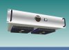
In front panel ,one current adjust pot ,Is that going to be a dimmer on the side of the model?
commonly adjusting all the four CXAs in operation,at same driving current ...
Yeap...
Dimmer pot -Spectrum toggle switch..
That's the Human interface ....
From indications only Amperage and Chip case temperature
In the back side it will have an On/Off Switch,the AC power socket and the reset button of a circuit breaker .
Last edited:
stardustsailor
Well-Known Member
I'm thinking on a similar solution ...Where are the feet to protect the COBs? I love that feature on your other lights.
Something better than tattoo ink caps ..
stardustsailor
Well-Known Member
Tried once to make a plant mover with a ....turnable ....Cool! What are your thoughts on automated plant or light movers?
Anyway ...The motor died soon ...Too weak to turn the-watered- pot ....
(Even if I had it 'geared' to turn the pot one whole 360 round / 18 or 12 hours .....)
Anyway ....
Dunno ...
I'm not in robotics ...(servo's and stuff ....) ..Yet ,i guess ...
stardustsailor
Well-Known Member
I think so ....This light is gonna be cool
It's a self protecting beast ....
And I'm sure ,it is going to help producing some fine weed ,for poor me !
stardustsailor
Well-Known Member
Dunno ...I got ...while trying to water ..LOL!I wonder whether plants get dizzy?
Like chasing a kid to eat it's lunch ....sort of ...
( Stupid ...I could have stood still and let the pot water itself around ...
 ...)
...)stardustsailor
Well-Known Member
Now ...
Can't sleep ...
( Awesome ...That white russian batch is awesome ! ) ...
And testing the " Thermal Monitoring ,Protecting and Active Fan Speed Control" ...
It responds fast and precise ...
Did some tests with the latest code ..
1) Tried to see when the full fan overdrive(>12 V ) begins,at which Tc ...
2) Check the Tc averaging routine ( for 4 operational chips ,in two "sets" / "modes " ,veg-flower spectrum)
3) Double check the Thermal Relay Protection operation ( if operates even for one Tc ) .
4) Try different fans (quality,brands ,power) ,to check if anyone is not "compatible" ...
(None ,so far ...tested over....Hmm mm....plenty ..enough )
5) Trim the fan kick-start ..(Power level-Duration )...
And few more things ...
It might take some final adjustments and refining ...
But seems to work really great ...
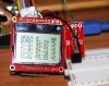
Vid notes :
-Long ,bad quality ,boring vid.Waste of time .
- Blue led is relay signal
-Blue 7seg led display is fan PWM voltage ...
-LCD display (probably you won't be able to see $h!t ,cause of the super-crappy quality of my mobile's camera ..)
shows 4x Tc at each operational mode...
-Solder iron tip is supposed to be the CXA's case ...
BOOOOOORRRRRRRINGGGGGG:
Can't sleep ...
( Awesome ...That white russian batch is awesome ! ) ...
And testing the " Thermal Monitoring ,Protecting and Active Fan Speed Control" ...
It responds fast and precise ...
Did some tests with the latest code ..
1) Tried to see when the full fan overdrive(>12 V ) begins,at which Tc ...
2) Check the Tc averaging routine ( for 4 operational chips ,in two "sets" / "modes " ,veg-flower spectrum)
3) Double check the Thermal Relay Protection operation ( if operates even for one Tc ) .
4) Try different fans (quality,brands ,power) ,to check if anyone is not "compatible" ...
(None ,so far ...tested over....Hmm mm....plenty ..enough )
5) Trim the fan kick-start ..(Power level-Duration )...
And few more things ...
It might take some final adjustments and refining ...
But seems to work really great ...
Vid notes :
-Long ,bad quality ,boring vid.Waste of time .
- Blue led is relay signal
-Blue 7seg led display is fan PWM voltage ...
-LCD display (probably you won't be able to see $h!t ,cause of the super-crappy quality of my mobile's camera ..)
shows 4x Tc at each operational mode...
-Solder iron tip is supposed to be the CXA's case ...
BOOOOOORRRRRRRINGGGGGG:
PetFlora
Well-Known Member
stardustsailor
Well-Known Member
LOL!!
Who would 've ever thought ,that it will be a time when grow lights will have a ..'brain' (sort of ....)
Anyway ..Nice find there Pet ...
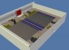
Some design Updates :
Due to space and weight restrictions ,the design has changed(once more ) quite enough ....
New Version Specs :
Light Source : 4x Cree CXA3070 3000°K -80CRI-Z4bin
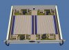
Heatsinks : 2x 200 x 160 x 40 mm ( LxWxH )
Fans : 4x 120 mm 5.4 Watt Sunon MagLev ( MEC0251V1-0000-A99)
Drivers :4x MeanWell HLP-80H-42
Fan/MCU PSU : MeanWell PS-45-15
Protection :
-EMI : AC Filter
-Inrush current : Class C resettable circuit breaker
-CXA Chip Over-heating : MCU controlled power cut-off ,through an industrial mount Solid State Relay (25A )
Case : Standard Rack Size (19" ) Blanck Steel/Aluminium 420 x 350 x 88 mm ( WxDxH )
Features :
-Driving Current of CXA Chips : Adjustable (common) , ~300 mA to 1950mA
-MCU controlled Fan Speed
-Individual CXA Case Temperature Monitoring ,
Displayed on LCD screen ,white led lit ,along with :
-Average operating Case Temperature
and
-Driving Current
-Hall effect Amperage Sensing.Sensor is not part of the CC circuit of the arrays.
-Hardware & Software sensor (Temperature & Amperage )Low-Pass filtering.
.......DIY meets High-End industrial design .
New 'screen'...Besides ,on the breadboard ,the ACS712 Low Current Sensor Board v14
http://www.sparkfun.com/products/8883
(Measure Range : 0-5000 mA )

Last edited:
stardustsailor
Well-Known Member
Unfortunately,while is doable (relatively easy ) ,it will mess with the cooling ,asThe only thing I notice that's missing is the ability to tilt each heat sink to direct the lights to provide better below canopy penetration
it will alter unevenly the air volume entering the air inlets (the sides perpendicular to the length of the heatsink )
and will ultimately change the path of the air channel ...There are a lot at stake ...
( Cool air will only enter the case ( as air-sealed as possible ) from the bottom side,from the fin openings of the heatsinks and from air inlets underneath where drivers are mounted,inside the case .(<=Although on purpose at tad "choked " ,not to lose overall "negative pressure " inside the case.Warm air will exaust from fan openings,on top lid of the case .
Fans are blowing outwards,not inwards.They "suck" air from bottom of case .Top lid of the case will be supported with alum bars ,riveted all along,to minimise vibrations ,that 4 x 5 Watt fans ,might cause while operating ,specially when overdriven .
All the inside side walls of the case ,as also the top lid will be internally covered with flame-retardant sound supressing foam ( enter=>Ricofon ),in order to minimise audible noise/vibrations coming from fans .
)
Last edited:
salmone
Well-Known Member
its for read...and take ideas...
https://github.com/FernandoGarcia -
Ferduino aquarium controller
Available in Portuguese, English, Spanish and French.
Easy to customize.FREE
1 x http://imall.iteadstudio.com/display...120419006.html
1 x http://imall.iteadstudio.com/prototy...120717001.html
1 x http://www.ebay.com/itm/Mega-2560-AT...item19d582a06b
2 x http://www.sureelectronics.net/goods.php?id=1020
1 x http://www.ebay.com/itm/New-16-Chann...item27c1368c78
more ideas...
http://code.google.com/p/jarduino-aquarium-controller/
jarduino-aquarium-controller
http://www.instructables.com/id/Creating-a-fully-automated-LED-growbox/
growbox
http://www.instructables.com/id/Backyard-Automated-Greenhouse/
Plantduino Greenhouse
http://gardenbot.org/about/
GardenBot
http://arduinogrc.blogspot.com.es/
Arduino Grow Room Controller
more ideas... on the typhon way...
http://shop.stevesleds.com/Typhon-Typhoon-LED-Controller-Typhon.htm
http://code.google.com/p/typhon-reef/
http://code.google.com/p/typhon-reef/source/browse/#svn/trunk/hardware/typhon
hardware
http://code.google.com/p/typhon-reef/source/browse/#svn/trunk/software
software
The code is for the basic version.
Steve's LEDs latest code is not publicly released.
We are able to provide you with the hex code, should you need to restore your Typhon to factory default firmware.
http://www.stevesleds.com/uploads/Typhon_LED_Controller_4114.pdf
...curious fan way......
http://shop.stevesleds.com/Pressurizing-Cooling-Fan-with-Power-Regulator-Pressurizing-Cooling-Fan-w-plug.htm
http://imall.iteadstudio.com/im130529001.html
[Bare PCB] Typhon Board
http://coralux.net/?wpsc-product=storm-led-controller-2
storm-led-controller
http://coralux.net/?wpsc-product=storm-x-led-controller
storm-x-led-controller
http://www.boostled.com/product_p/typhon.htm
Typhon LED Controller
http://cdn.shopify.com/s/files/1/0055/9572/files/TyphonControllerManual.pdf
Typhon LED Controller Kit Manual
http://coralux.net/?p=213
development of a 0-10V PWM controller
http://www.nano-reef.com/topic/321511-typhon-based-led-controller-on-the-cheap-seriously/
Typhon-based LED controller on the cheap (seriously)
http://www.plantedtank.net/forums/showthread.php?t=603658
2surplus's 6' New LED Build.
http://www.plantedtank.net/forums/showthread.php?t=183131
Calling all DIY LED "Junkies" - Your opinions wanted!
http://www.reefcentral.com/forums/showthread.php?t=2310459&page=2
Has anyone made an LED driver based on LM3463 6 channel driver IC?
http://www.plantedtank.net/forums/showthread.php?t=136148
DIY PCB's for DIY LED Systems.
http://www.plantedtank.net/forums/showthread.php?t=139167
Just built a DIY LED Controller
http://www.plantedtank.net/forums/showthread.php?t=152852
built another DIY led driver!
http://www.plantedtank.net/forums/showthread.php?t=120109
DIY PAR meter, Yeah you heard me
http://www.reefcentral.com/forums/showthread.php?t=1759758
DIY LED driver for reef lighting
http://www.plantedtank.net/forums/showthread.php?t=519649
DIY "Knob Dimmer" for PWM based LED drivers.
http://www.plantedtank.net/forums/showthread.php?t=243562
A Cheap, Simple, Compact DIY LED Controller/Driver COMBO.
http://www.reefcentral.com/forums/showthread.php?t=2222702
Meanwell LDD driver: for those who want to dim to 0 using Arduino
pardon if i hijack this thread its for your reads sds... i hope you understand me a litle bit...
Last edited:
churchhaze
Well-Known Member
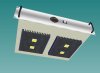
Why not just use the 7-segment display with a tactile push button to toggle through outputs, and use indicator led's and a faceplate to let the user know which number is being displayed? A buzzer of some sort can alert the user if any of the temperatures get to high.
Do you really need the LCD?
I really like the project (I'm way too lazy to apply myself like you do), but sometimes it seems like you include devices for devices sake.
(I guess this was already discussed? I have volatile memory and somebody turned me off)
Here's an example of what I mean (found on google images, not mine. I'm actually not sure what this thing is other than 4x7segments with a bunch of indicator leds.)
Last edited:

stardustsailor
Well-Known Member
ok ...
Just came back home ,from a short Easter holiday trip ...
Lot's of things to at home and not much time ....
But I can't resist ....
So ...
Just came back home ,from a short Easter holiday trip ...
Lot's of things to at home and not much time ....
But I can't resist ....
So ...