Thinking of a new light ..

stardustsailor

Well-Known Member
I go with louder than normal fans because I listen to music throughout the house all day with surround in each room. I'll post my new design when it's done :)

lol

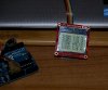
The temp resistor I had in mind was this
https://www.sparkfun.com/products/10988
It cost two dollars but I bet in bulk of 10 you could go to 1.50. I have personally held a flame on this until it hit 100*C without a problem. So place it touching the CXA on the outside through the hole you will probably drill for the CXA wires anyway. Easy. Cheap :)

Osram suggests K type thermocouples glued with thermal epoxy...(can't be soldered..Alloy won't allow.)
Cree suggests T type type soldered ...


tc.JPG


TMP36 - Temperature Sensor

  • 10 mV/°C scale factor
  • ±2°C accuracy over temperature
  • ±0.5°C linearity
  • Operating Range: −40°C to +125°C
Thermocouples .
Type J
Type J (ironconstantan) has a more restricted range than type K (−40 °C to +750 °C), but higher sensitivity of about 50 µV/°C.[2] The Curie point of the iron (770 °C)[9] causes a smooth change in the characteristic, which determines the upper temperature limit.

Type K
Type K (chromelalumel) is the most common general purpose thermocouple with a sensitivity of approximately 41 µV/°C (chromel positive relative to alumel when the junction temperature is higher than the reference temperature).[10] It is inexpensive, and a wide variety of probes are available in its −200 °C to +1350 °C / -330 °F to +2460 °F range. Type K was specified at a time when metallurgy was less advanced than it is today, and consequently characteristics may vary considerably between samples. One of the constituent metals, nickel, is magnetic; a characteristic of thermocouples made with magnetic material is that they undergo a deviation in output when the material reaches its Curie point; this occurs for type K thermocouples at around 350 °C.

Type K thermocouples may be used up to 1260 °C in oxidizing or inert atmospheres without rapid aging. In marginally oxidizing atmospheres (such as carbon dioxide) between 800 °C–1050 °C, the chromel wire rapidly corrodes and becomes magnetic in a phenomenon known as "green rot"; this induces a large and permanent degradation of the thermocouple, causing the thermocouple to read too low if the corroded area is exposed to thermal gradient.[11] Another source of drift in type K thermocouples is that near 400 °C, a slow reordering in the chromel wire occurs; this is reversible and leads to hysteresis between heating and cooling.

Type T
Type T (copperconstantan) thermocouples are suited for measurements in the −200 to 350 °C range. Often used as a differential measurement since only copper wire touches the probes. Since both conductors are non-magnetic, there is no Curie point and thus no abrupt change in characteristics. Type T thermocouples have a sensitivity of about 43 µV/°C. Note that copper has a much higher thermal conductivity than the alloys used in thermocouple constructions, and so it is necessary to exercise extra care with thermally anchoring type T thermocouples.

......


Slow,innacurate,not sensitive enough ....
Don't you think ...?
Leds need only thermocouples for accurate and fast Temp measures ...
(Almost x1000 times more sensitive than the TMP 36 )
Nothing else can beat'em ....
 

CannaBare

Well-Known Member
Osram suggests K type thermocouples glued with thermal epoxy...(can't be soldered..Alloy won't allow.)
Cree suggests T type type soldered ...


View attachment 3127449


TMP36 - Temperature Sensor

  • 10 mV/°C scale factor
  • ±2°C accuracy over temperature
  • ±0.5°C linearity
  • Operating Range: −40°C to +125°C
Thermocouples .
Type J
Type J (ironconstantan) has a more restricted range than type K (−40 °C to +750 °C), but higher sensitivity of about 50 µV/°C.[2] The Curie point of the iron (770 °C)[9] causes a smooth change in the characteristic, which determines the upper temperature limit.

Type K
Type K (chromelalumel) is the most common general purpose thermocouple with a sensitivity of approximately 41 µV/°C (chromel positive relative to alumel when the junction temperature is higher than the reference temperature).[10] It is inexpensive, and a wide variety of probes are available in its −200 °C to +1350 °C / -330 °F to +2460 °F range. Type K was specified at a time when metallurgy was less advanced than it is today, and consequently characteristics may vary considerably between samples. One of the constituent metals, nickel, is magnetic; a characteristic of thermocouples made with magnetic material is that they undergo a deviation in output when the material reaches its Curie point; this occurs for type K thermocouples at around 350 °C.

Type K thermocouples may be used up to 1260 °C in oxidizing or inert atmospheres without rapid aging. In marginally oxidizing atmospheres (such as carbon dioxide) between 800 °C–1050 °C, the chromel wire rapidly corrodes and becomes magnetic in a phenomenon known as "green rot"; this induces a large and permanent degradation of the thermocouple, causing the thermocouple to read too low if the corroded area is exposed to thermal gradient.[11] Another source of drift in type K thermocouples is that near 400 °C, a slow reordering in the chromel wire occurs; this is reversible and leads to hysteresis between heating and cooling.

Type T
Type T (copperconstantan) thermocouples are suited for measurements in the −200 to 350 °C range. Often used as a differential measurement since only copper wire touches the probes. Since both conductors are non-magnetic, there is no Curie point and thus no abrupt change in characteristics. Type T thermocouples have a sensitivity of about 43 µV/°C. Note that copper has a much higher thermal conductivity than the alloys used in thermocouple constructions, and so it is necessary to exercise extra care with thermally anchoring type T thermocouples.

......


Slow,innacurate,not sensitive enough ....
Don't you think ...?
Leds need only thermocouples for accurate and fast Temp measures ...
Nothing else can beat'em ....
I guess from what I've seen with stoners and With myself being a super stoner. We do things simple, easy and cheap and they work. I understand what the recommendation for a "Thermocouple" is. What I am saying is "Hey! You are only letting them get up to 100*C so just go with a cheap temp sensor that reads through analog."

At first when I bought the CXA3050 I measured temp by coiling a wire and attaching to the thermocouple to draw the heat and measure with an IR temp gun. Now I just touch the temp sensor, I bought for 2 dollars, to my casing and I get what I would say is an exact measurement of temperature of my case, Which is 55*C. I could glue it next to the casing on the heatsink permanently and never worry about it breaking, but I touch it instead because that is easier.

I just think why worry about green rot and gluing a thermocouple when you can place the sensor next to it and get a pretty right on reading. :)
 
Last edited:

stardustsailor

Well-Known Member
I agree with you on the kits. I used to feel the same way about arduino itself. (i learned on 68HC11 lol)

Read the giant datasheet for the microcontroller on the arduino you're going to get so you can see how all the peripherals are laid out and how the AVR architecture works, then using the arduino itself will make a bit more sense.

If you have a design with a ton of i/o , you may want to consider the atmega 1286/2560. They're a bit more expensive/bigger, but have way more I/O.

I got a resistor kit that had 10 of each common resistor size, 1% tolerance, and a similar capacitor kit (came with extra of the more common electrolytics), this way I have all I need laying around for prototyping. I got arrays of tiny plastic drawers to store each resistor/capacitor size in, and labeled each drawer.
Analog also ?
Have to check the datasheets ..
Thanx ...
 

stardustsailor

Well-Known Member
Another ( cheap as possible ) solution is this :
P4131033.JPG

Four K type thermocouples ...
And a Quatro-Throw ,triple Pole rotary switch ...
( Throw: The number of pins contacting to poles ....Pole: number of (isolated amongst them ) 'common' pins .Aka poles )

Pole one : Yellow of thermocouple ,output to arduino's shield.
Pole two: :Red of thermocouple , output to arduino's shield
(optional ) Pole three : +12/15 VDC with a 1K resistor before pole.

Set of four pins #1 : The yellows of the four thermocouples
Set of four pins #2 : The reds of the four thermocouples
(optional )Set of four pins #3 : four indicator leds ( "dice "-like posotioned,to resemble the four heatsinks/chip operational modules ),connected commonly to Ground (-) ...

Switch has four positions ..At each position the display will show the case temperature of each one of the four chips,respectively ..

Notes : Extending the Wiring,of thermocouples,needs the pair of (copper)wires to be of exact same material ,
diameter and length,as they can alter the Voltage differential ,created between the two alloys of the thermocouples and being measured and translated into temperature ......

A kinda better solution ,than before ...

( They need at least three analog inputs from microcontroller, per thermocouple ..
So to have each thermocouple real-time monitored ...At least 12 analog inputs and pretty good processing power /speed ..
 

churchhaze

Well-Known Member
There are 16 10-bit analog inputs on the arduino mega (atmega 1286/2560). I'm actually not sure what the smaller ones have. I agree with cannabare that the attiny's are probably best to use when trying to minimize cost if the extra I/O and peripherals aren't needed. I just don't know mang. I'm a super stoner.

Analog also ?
Have to check the datasheets ..
Thanx ...
 

stardustsailor

Well-Known Member
There are 16 10-bit analog inputs on the arduino mega (atmega 1286/2560). I'm actually not sure what the smaller ones have. I agree with cannabare that the attiny's are probably best to use when trying to minimize cost if the extra I/O and peripherals aren't needed. I just don't know mang. I'm a super stoner.
I agree a lot with Cannabare and in more than that one ,but at this case extra I/O and peripherals are needed.
Period .
The smallest MC that can be used I think is the 328 ..(from the AVR family ,at least
..Never used anything other ,like PIC ..
Haven't reached THAT far ... )

But ...

Is not like making a simple thermometer here ...
It needs to be really precise ,fast responding,sensitive and accurate ...
It has to be a lab-grade measuring device ....
Imagine that ....
Temp is changing (quick enough !! ),as I'm approaching (not touching .) my hand's palm to the tip of the thermocouple ...
2" away !!! And is measuring the heat radiated by my hand !
Truly amazing !
Way sensitive !
For a sensor with a range of -200C to +1350C !!!!
 
Last edited:

stardustsailor

Well-Known Member
I guess from what I've seen with stoners and With myself being a super stoner. We do things simple, easy and cheap and they work. I understand what the recommendation for a "Thermocouple" is. What I am saying is "Hey! You are only letting them get up to 100*C so just go with a cheap temp sensor that reads through analog."

At first when I bought the CXA3050 I measured temp by coiling a wire and attaching to the thermocouple to draw the heat and measure with an IR temp gun. Now I just touch the temp sensor, I bought for 2 dollars, to my casing and I get what I would say is an exact measurement of temperature of my case, Which is 55*C. I could glue it next to the casing on the heatsink permanently and never worry about it breaking, but I touch it instead because that is easier.

I just think why worry about green rot and gluing a thermocouple when you can place the sensor next to it and get a pretty right on reading. :)
Well ...No a bad point ,there ...
Hmmm..Now,you got me thinking ...

Simple temp sensor ,eh ?
...
 

CannaBare

Well-Known Member
I agree a lot with Cannabare and in more than that one ,but at this case extra I/O and peripherals are needed.
Period .
The smallest MC that can be used I think is the 328 ..(from the AVR family ,at least
..Never used anything other ,like PIC ..
Haven't reached THAT far ... )
How many pins do you need overal? The thermocouple needs 3 you said? Also what is the shield for?
 

stardustsailor

Well-Known Member
Another good option -and cheap- is four thermistors/silistors ...
They are super linear,sensitive and fast responding passive components .
All they'll need is the +5V from Aref pin,and one 10-bit analog input each ...
(Althought ..with reading 4 analog inputs,simultanouesly ,noise does become an issue ...)
The tricky part is to define/find which one(type ) is appropriate for measuring Tcase of the CXAs ...
 

stardustsailor

Well-Known Member
I think I will go the 6x silistor/thermistor way +Arduino ...
Monitoring the Tcase of all the six CXA chips on board !

P4141037.JPG

Based on Adalfruit's small ,neat,code,I'm writting a more 'complex' for six NTC 1% (or even 0.1% if I'll find any ! )
thermistors ..
All the analog inputs,of the Arduino , are used ( A0-A5 )..
Temps shown are random ,cause of open inputs ...and noise ...
Tc=Temperature Case
30A = 3000K CXA chip #1
30B = 3000K CXA chip #2
50A/B=5000K chips
27A/B=2700K chips
All the CXAs will be monitored this way ...
With satisfactory precision...
At least ,rig will shutdown if any of the TC gets higher than 90-95 C ....
That's the main purpose of it ,anyway ....

A bit of programming left ...
The relay part ....

 
Last edited:

SNEAKYp

Well-Known Member
Cob holders are the way to go. My molex ones had me stress free putting it on. I like yours though, not too much plastic.
 

safety meeting

Active Member
Could you answer 2 questions from a noob if you don't mind.

#1 How are you measuring the spread and intensity of your individual cobs? Seems like most are using a light meter to gauge and then test? or is there a formula to predict based on vF..A's and Tj temp?

I ask because I want to run some Vero 18's and soft @ around 600mA apiece, but I have no idea how to calculate vertical and horizontal [disco effect] spreading....

#2 Have you ever pondered using the Arduino as the pwm controller for controlling an entire light period? That is taking a favorite latitude for instance and applying that to your light source? Nice cool mornings, 20% random breeze etc. 15% random shading over the 1st 4-6 weeks low uv-a until noonish and maybe a little higher traces of <600nm. Then at noon time, an increased amount of UV-a with a change to yellow into red. Then a finish into darker reds and a cool-down mimicing sundown?

You see this kind of setup with corals and aquaria and such, It may be irrelevant, but it seems that a full as possible spectrum mimmicing a known source with variable throughout the day, is at least something to be studied or pondered?


Thank you for your threads, nothing else out there comes close to the knowledge here..........so very good!
 

stardustsailor

Well-Known Member
Could you answer 2 questions from a noob if you don't mind.

#1 How are you measuring the spread and intensity of your individual cobs? Seems like most are using a light meter to gauge and then test? or is there a formula to predict based on vF..A's and Tj temp?

I ask because I want to run some Vero 18's and soft @ around 600mA apiece, but I have no idea how to calculate vertical and horizontal [disco effect] spreading....

#2 Have you ever pondered using the Arduino as the pwm controller for controlling an entire light period? That is taking a favorite latitude for instance and applying that to your light source? Nice cool mornings, 20% random breeze etc. 15% random shading over the 1st 4-6 weeks low uv-a until noonish and maybe a little higher traces of <600nm. Then at noon time, an increased amount of UV-a with a change to yellow into red. Then a finish into darker reds and a cool-down mimicing sundown?

You see this kind of setup with corals and aquaria and such, It may be irrelevant, but it seems that a full as possible spectrum mimmicing a known source with variable throughout the day, is at least something to be studied or pondered?


Thank you for your threads, nothing else out there comes close to the knowledge here..........so very good!
#1 Personally I do not do such measurements ..
I do some 3D light modelling and some RAY modelling ,but thats how far I've gone ,regarding that issue ...

Mr Flux and SupraSPL ,are more specialists in those matters ...

#2 You just can't imagine ,what iI've ' pondered ' to do with that little blue thing ...
All these that you mentioned ,once was a "to be done " project for me ...
And then I lost my job ,things got rough for everyone around here ..
Anyway ..
Yes ...
Many things ...
 

stardustsailor

Well-Known Member
Ok ...

This light is going to be something else ..
back to minimalism (outside at least )

In front panel ,one current adjust pot ,
commonly adjusting all the four CXAs in operation,at same driving current ...

One amperemeter ,just to indicate the driver's output current ...
(Taken from one random drivers ,but since all are of the same type,powered from same AC line,and adjusted by one common pot ,any difference in output should be negligible)..


And one LCD panel ,white led lit,indicating Case temperatures of the chips in operation ...
(Behind dark tinted PMMA (plexi ),inside the box ...Wow!!!)
........

Mode A : Veg -growth-protein biosynthesis enhancing light spectrum :
P4171056.JPG
And ....
Mode B : Bloom -production-flowering-carbohydrate biosynthesis enhancing light spectrum :
P4171057.JPG


And featuring of course top-notch material and parts ,like MeanWell power supplies ( CV & CC )
and six awesome Cree CXA3070 ...

Also an active chip case monitoring system ,with thermal protection and
a Floating Feedback Closed-loop Cooling system,which controls constantly the fan speed,
(and a 5" "hot" kick-start when fixture will switch on ... ),
depending on the average Tc of each of the four operational chips ..
(the 'pair' that remains switched off at each mode ,is not averaged .(not calculated)


Testing the rig :

 
Last edited:
Top