MeanWell LED Drivers: 3 in 1 Dimming Function.
- Thread starter stardustsailor
- Start date
So if I would put the Dim+ to the left post of the potentiometer, the Dim- to the middle one and the left wire post stays free it will work?100k potentiometer
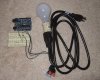
Wire post #1 to blue wire
Wire post #2 to white wire
This is how mine is wired and works OK
sorry I mean the right wire post stays freeSo if I would put the Dim+ to the left post of the potentiometer, the Dim- to the middle one and the left wire post stays free it will work?
Thank you, you helped me a lot!!That's correct
SupraSPL
Well-Known Member
Ran into a problem dimming 4 drivers with a 25K pot. The customer wants to be able to switch off each driver. The problem is, when I switch off the power to one of the drivers, the whole system goes to about 1/4th power. Apparently the other drivers do not like being tied in with an unpowered driver's dimming circuit.. So my compromise/solution is to put one driver on its own dimmer so at least one can be switched off and the other 3 can be dimmed together.
Another solution would be to use an additional double throw switch to disconnect each driver from the others in the dimming circuit when power is switched off. But that would require a 100K pot, resulting in the entire dimming action being 1/4 of a turn most of the time.
So if you expect to be turning certain drivers off periodically, individual dimming might be the way to go.
beodrone
Active Member
What about using an arudino - hook the POT up to a analog input and then drive the 4 dimmers individually off arduino outputs? Might require a voltage doubling circuit but SDS kindly laid that out earlier in this thread ")
Could add some switches on 4 other inputs to turn each light on/off completely.
Could add some switches on 4 other inputs to turn each light on/off completely.
bicit
Well-Known Member
Depends on how far away the driver needs to be mounted. The light I'm building for a customer requires the driver be mounted in a totally different room. PWM signals wouldn't work in that instance without over complicating things. Although the idea of being able to dim the lights through a smart phone app is intriguingWhat about using an arudino - hook the POT up to a analog input and then drive the 4 dimmers individually off arduino outputs? Might require a voltage doubling circuit but SDS kindly laid that out earlier in this thread
Could add some switches on 4 other inputs to turn each light on/off completely.
This thread has a hell of a lot of information. Thank you very much!!
Can someone please confirm if I am on the correct path?
I have two HLG-120H-C1050 CB drivers on 4 CXB3590 72V COB's (300W). From what I can gather, all I need to do is wire in a 50KΩ linear pot and 5K resistor as per this SDS post (with the resistor on the negative side of the pot before, the first driver)? Do I need to worry about the 3rd pin on the pot (ground I think)?
This might also answer Jammes333 post above. Except he may require a 47KΩ and a 3.6K resistor as per the table below (stolen from earlier in the thread). So just the same as what I need essentially. (Don't listen to me James, this is more of a question than an answer).
Number of drivers ____Pot value___Dis.Power.______LowLimiter Value10%____
2 50KΩ 10mW 5K
3 47KΩ 15mW 3.6 K
4 25ΚΩ 20mW 2.5K
5 20KΩ 25mW 2K
6 20KΩ 30mW 1.6K
I don't have a great grasp on this yet so was just going off that table in my post above. How do you get to 33K for 3?You are correct, for 2 drivers a 50K pot and no worries about the third pin or where the resistor goes.
For 3 drivers wouldnt it be 33K?
apoulin
Well-Known Member
First off thank you SDS, fantastic info here. I learn more from you than half of my professors lol Consider your tuition check in the mail
I have an Arduino Uno and am very interested in being able to control my Meanwell HLG-185H-C1400B with the PWM pin. After reading everything it seems as though I could hook it up and dim all the way down to 10%, can I not dim to 0%? Or am I reading the previous info wrong?
I just wanted to be able to turn my lights on/off via my arduino, I looked at the data sheet and it said that the driver could only be dimmed to 0% using a circuit that you already have posted on the first page and NOT by using just a POT.
I have been reading that I could hook both of my drivers up to a relay and use my arduino to control the relay, but that requires tapping into the high voltage plug from the drivers. So I thought if I could hook the driver up to my arduino via the dimmer that it would be a much safer growing/learning environment
I have two Meanwell drivers, one has dimming capabilities, the other does not (LPC-60-1400) which is why I was thinking of the relay solution until I came across this wealth of info, now I may just use the dimming function of my driver and only purchase dimmable drivers in the future.


EDIT:
Relay idea I was talking about
http://www.glacialwanderer.com/hobbyrobotics/?p=9
OR (Just stumbled upon)
https://www.sparkfun.com/tutorials/119
I have an Arduino Uno and am very interested in being able to control my Meanwell HLG-185H-C1400B with the PWM pin. After reading everything it seems as though I could hook it up and dim all the way down to 10%, can I not dim to 0%? Or am I reading the previous info wrong?
I just wanted to be able to turn my lights on/off via my arduino, I looked at the data sheet and it said that the driver could only be dimmed to 0% using a circuit that you already have posted on the first page and NOT by using just a POT.
I have been reading that I could hook both of my drivers up to a relay and use my arduino to control the relay, but that requires tapping into the high voltage plug from the drivers. So I thought if I could hook the driver up to my arduino via the dimmer that it would be a much safer growing/learning environment
I have two Meanwell drivers, one has dimming capabilities, the other does not (LPC-60-1400) which is why I was thinking of the relay solution until I came across this wealth of info, now I may just use the dimming function of my driver and only purchase dimmable drivers in the future.
EDIT:
Relay idea I was talking about
http://www.glacialwanderer.com/hobbyrobotics/?p=9
OR (Just stumbled upon)
https://www.sparkfun.com/tutorials/119
Attachments
-
 144.8 KB Views: 102
Last edited:
Rahz
Well-Known Member
I'm trying to source a low current limiter, but am having trouble finding a part that would be appropriate for a potentiometer, 50Kohm specifically. Can anyone give me a lead?
Attachments
-
![Pot way[1].jpg](/data/attachments/2515/2515300-dbf2fdd7294ce6436c68226966ccad14.jpg) 185 KB Views: 84
185 KB Views: 84
robincnn
Well-Known Member
1/4 watt 10k ohmI'm trying to source a low current limiter, but am having trouble finding a part that would be appropriate for a potentiometer, 50Kohm specifically. Can anyone give me a lead?
http://www.mouser.com/ProductDetail/Ohmite/OD103JE/?qs=sGAEpiMZZMuDPtTs5Gda2wcLJqyBp4LZpiTg6hnJOFI=
Not sure if 5k ohm might be better since u using 50k pot
You can filter any specific value of resistor u want on mouser
Rahz
Well-Known Member
Thank you! So, it's just a resistor? I'm learning as I go...1/4 watt 10k ohm
http://www.mouser.com/ProductDetail/Ohmite/OD103JE/?qs=sGAEpiMZZMuDPtTs5Gda2wcLJqyBp4LZpiTg6hnJOFI=
Not sure if 5k ohm might be better since u using 50k pot
You can filter any specific value of resistor u want on mouser
I think 5K or 10K would be fine... I don't foresee the need to run a 300w lamp at 30 watts.
salmonetin
Well-Known Member
...other posible way for automated control (arduino way,,,. contactors + timmers way...) its substitute the 12-pole rotary switch with 12 channel reles and a pcb with all resistors circuit/s... ...another resistive scaled dimming way... ...i saw 16 channel reles (or 6+6)...not too expensives actually... maybe with SSRs...crazy idea?...Resistive dimming with either utilising a pot (smooth linear dimming) or a rotary switch (pre-set adjustments )
is mainly applied for MANUAL dimming-controlling of LED driver(s).
For AUTOMATED dimming-control ,
then the Pulse Width Modulated dimming option should be used .
Automated control can be achieved ,using the resistive way ( via digital potentiometer IC ),
but extra circuitry and components are needed.Cost is increased also.
So it stays -far - aside ...
pd... thanks Pos...
pd1... or add another switch (manual or auto) and go for both... in my mind see one extra control box for arduino and reles etc for your lamps...
saludos
Last edited:
robincnn
Well-Known Member
50k pot with 5 or 10k ohm resistor just as you had in the image. Mouser has many options for 50k pots but expensiveThank you! So, it's just a resistor? I'm learning as I go...
I think 5K or 10K would be fine... I don't foresee the need to run a 300w lamp at 30 watts.
In recetly ordered some cheep once on eBay
Just search '50k ohm potentiometer'. I made sure it said linear taper
EBay has 1/4 watt 10k ohm carbon resistor too
I wonder if a dual taper 100k pot can be used to control 2 drivers. Upper connector for one driver and lower for 2nd driver
http://www.ebay.com/itm/100K-OHM-Linear-Dual-Taper-Rotary-Potentiometers-B100K-100KB-POT-ALPHA-/260944291837?pt=LH_DefaultDomain_0&hash=item3cc17de7fd