MeanWell LED Drivers: 3 in 1 Dimming Function.

stardustsailor

Well-Known Member
Get to know Transistors

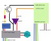
Transistors amplify current, for example they can be used to amplify the small output current from a logic IC so that it can operate a lamp, relay or other high current device.

-In many circuits a resistor is used to convert the changing current to a changing voltage, so the transistor is being used to amplify voltage.(later on that ..Automated ,Analog signal ,via Voltage Dimming ..)

-A transistor may be used as a switch (either fully on with maximum current, or fully off with no current) and as an amplifier (always partly on).

The amount of current amplification is called the current gain, symbol hFE.

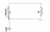
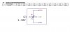
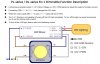
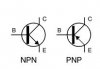
There are two types of standard transistors, NPN and PNP, with different circuit symbols. The letters refer to the layers of semiconductor material used to make the transistor.
Most transistors used today are NPN because this is the easiest type to make from silicon.
If you are new to electronics it is best to start by learning how to use NPN transistors.
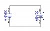
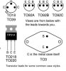
The leads are labelled base (B), collector (C) and emitter (E).

These terms refer to the internal operation of a transistor,
but they are not much help in understanding how a transistor is used,
so just treat them as labels!

tr1.JPG


.......

tr cs.JPG
....
http://electronicsclub.info/transistorcircuits.htm#model
http://electronicsclub.info/transistors.htm

----------------------------------------------------------------------------------------------
 

stardustsailor

Well-Known Member
Typical transistors used as switches ,interfacing microcontrollers like Arduino ,
but for low currents only (up to 100-200 mA ) ,are the BC547 and the 2N3904.

The BC547 is better as a 'power switch' for small indicator leds ,remote TTL control of other sub -circuits / IC's and
other small devices like small relays ,bazzers ,etc ...

http://www.fairchildsemi.com/ds/BC/BC547.pdf

The 2N3904 is better for fast switching ,like PWM signals ,
as it has low "delay" ,"rise","storage" and "fall" times ,as a switch .
And outputs low levels of noise.
(Minimizes "false triggering" ,during PWM control. )

http://www.fairchildsemi.com/ds/2N/2N3904.pdf


Arduino Uno can "sink" or "source " about 40mA per I/O .
So at the (software set ) PWM signal output pin ,
when Arduino signals high ,
there's a +5 VDC dynamic difference to Ground
and Arduino can source up to 40mA to drive a sub -circuit .


Since the PWM signal is 'positive' voltage in relation to Ground ,
to 'interface' it with the +10V DC voltage regulator ,
a NPN (Negative-Positive-Negative) transistor should be used.

As "Base" is positive ,it will accept the positive signal from Arduino.
Both Emitter and Collector ,are negatives ,so both are considered as "ground" .
That means ,that the actual Switching ( via PWM signal) is not done in the " Live " line (+10VDC )
but actually to the 'Ground' !
Ground line is switching on and off ! ( Ground PWM )

Using a NPN transistor ,a positive " high " PWM signal ,
gets transformed into "Ground" pwm signal .
(And Not 'negative ',thus -5 VDC ...)


So a constant +10VDC power supply (7810 voltage regulator sub circuit ) is 'closing'
with Ground ,via a NPN transistor ,(at Ground rail) .
The transistor's base is 'controlled' by
a +5V voltage signal from Arduino .
block dia 1.jpg


Black : Common Ground.

**(Actually the black line after transistor's collector ,going to Dim- ,
if shorted to common ground ,
will cancel out the PWM control and the driver will output then ,
maximum rated Io .)


Red : +12 VDC
Yellow: +5 VDC TTL
Amber : +10 VDC

Grey : Led Out - .Never short / connect with Common Ground OR ANYn +VDC.
Dark Pink: Led Out+ : Never short / connect with Common Ground OR ANY +VDC .

In order to protect the Arduino 's PWM output pin from being destroyed,
a current limiting Resistor {Rb } should be installed between PWM pin and Base pin of the transistor .(Typical Value range : 1K -10 K .
A resistor of 4.7 will be most appropriate ,for most small switching transistors.


More info:

"Choosing a suitable NPN transistor"
http://electronicsclub.info/transistorcircuits.htm#model
" Choosing a transistor"
http://electronicsclub.info/transistors.htm#choosing
 
Last edited:

stardustsailor

Well-Known Member
Before ,continuing further with Automated dimming control,
let's see how actually the '3in1 dimming Function" works ....

Let us ' imagine ' this :
exmple 2.JPG


Pos is Dim+ and Neg is Dim- .
R1 is the dimming resistor.

If the circuit was open ,then no current will flow through R1 to Ground .(Dim-)
Driver will output current Io=100% of Rated

Same if R1= 100K .

Rd=R1 = Vd/Id =>
100K =10V / Id =>
Id = 0.0001 A = 100uA .

So if a current of 100uA or less is flowing between Dim+ & Dim- ,then
driver will output Io=100% .


Every K increase of R1 is 1 % increase of Io (<=* for single driver apps )

If R1= 10K ,then
Id = 10V/ 10000 ohm= 0.001 A = 1mA .

If R1=1K then Id = 10V / 1000 = 0.01 A =10mA
if R1 =1 Ohm then Id = 10 A !!!
If Ri= 0 ohm ,then Id = ∞ A .
Theoretically that will destroy instantly , the dimming circuit of the driver.
Not a very good idea to short the Dim+ and Dim+ .


MeanWell suggests as min limit the 10% of rated max Io .
So max value of Id can have is 1 mA (1000 uA ) .

So the driver's ' 3in 1 ' dimming function ,
actually measures the current flowing between Dim+ and Dim- wires.

From 1 mA down to 0.1 mA or less or no current at all .
The more current flowing ,close to 1mA ,the drivers dims down towards min . limit of 10%*Io_max.
The less (or none) current flowing to a min of 100 uA ,then the driver increases Io towards 100% of rated max.


1mA = 10 % of Io_max
=< 0.1 mA = 100% of Io_max


Linearly ....
So 0.75 mA = 75% of Io_max ....

That is the basic operating principle.
Here explained using a resistor .

Instead of a resistor ...
External Voltage can be applied also .
But in what ways can be this done and how it actually works ?


stardustsailor

Well-Known Member
Καταγραφή.JPG

Would it work if we just connect a variable 1-10 VDC power source in series with Dim- & Dim+ ?
Is it just my nose or really something smells " burned" here ?
-------------------------------------------------------------------------------------------------


lmi3.JPG


dvc170.JPG


dmi323.JPG
 
Last edited:

stardustsailor

Well-Known Member
So let's go a step back to resistor dimming again.....

exmple3.JPG


This time a second external variable voltage source is connected to the resistor ,
parallel to the +10 VDC of Dim circuit of the driver.

That external variable voltage source -for now -has a dynamic diff = 0 .
No voltage .

The current that flows through the resistor is Id = 10 V / 10 K = 0.001 A = 1 mA .

(leds will be dimmed down to 10% of Io_max )

We set the external voltage to be +5V .

Now,some current will flow from the + 10V Dim source to the lower +5V external source ...
Since both the resistor and the external voltage source are in parallel connected to
Dim voltage source of the driver ,they ought to have the same voltage drop sum,
at their "ends" as the Dim source.
And since the external voltage source has +5V ,then the resistor must have the same exact Vf ,across it's pins .( 5v+5V =10 V )

But now Id = 5V / 10K = 0.0005 A = 500uA ...

Leds will be driven at 60% of Io _ max

Remember :
10K=1000uA=10% Io_max
20K=900uA=20% Io_max
30K=800uA=30% Io_max
40K=700uA=40% Io_max
50K=600uA=50% Io_max
60K=500uA=60% Io_max
70K=400uA=70% Io_max
80K=300uA=80% Io_max
90K=200uA=90% Io_max
100K = 100uA=100% Io_max
Applying an external voltage of +5V,parallel to the Dim +10V source ,
has the same effect as adding an 50K resistor in series to the 10K one .


If V external = 9 V ,then Id = 1 V/ 10K = 0.1 mA =100uA
Driver will output the max rated current ...
At 9 V ....
Why ?
Because of the resistor ....

If there was not any resistor just a plain 'short' aka ' bridge' ,then at + 10V ,
at the external source's terminals will cancel any current flowing ,over the 'shorted ' Dim+ and Dim- terminals .
Driver then will be outputting 100% of Io_max.

Of course always dimmers have an internal resistance ,as lower limiter and
they switch off totally the drivers via relay (s) .Not by shorting Dim+ or Dim- .

Another way is to have a minimum voltage level at the external voltage source.
Not 0-10 V but ,say 1-10 V ....That will be 10-100% dimming .It's like having a 10K
low limiter ...

On DIY design's it's preferable either of ways to be used as limiting the lowest dimming point.
Either the 'passive' way of using a 10K resistor ,or either the 'active' way of the dimming
external source to have a lowest voltage limit of 1 Volt . ( For pwm = 10% duty cycle )


So...
That is the basic principle of Voltage Dimming .

On same operation ,the PWM dimming is based .
As ,regarding a PWM square signal , it stands Vpwm = Vin * DutyCycle

Since Vin for pwm is 10 volts (same max as in Voltage dimming ) ,
then Vpwm = 10 * DutyCycle ....

20% duty Cycle ?
Vpwm= 10 * 0.2 = 2 V
100% duty cycle ?
Vpwm = 10V
35% duty cycle ?
Vpwm = 3.5 Volt ...
And so on .....
 
Last edited:

stardustsailor

Well-Known Member
The difference between PWM and voltage dimming in Automation is mainly one .

Pwm dimming is done by ' digital ' ( Low : 0-0.8 V / High: 2-5 V ) Square Signal.

To form a sinusoidal waveform dimming ,for example
(leds to go bright and dim ,over time following a sinusoidal waveform power 'pattern' )
using PWM signals ,can be done through programming only .

For example :
Duty cycle = 100 * ( a + sin ( x * T ) )
Where
0 =< ( x * T ) <= 90
a= lower limit


While at Voltage dimming , a "Function Generator" circuit can control the driver(s) directly ,
by applying an analog voltage waveform (like the signal going to audio speakers ,sort of )
no matter the shape (sinusoidal -triangle-sawtooth -square -noise- etc ) ,
as long it peaks at +10 V and has a lower limit of +1V ...
( And a frequency-way-way- less of 100Hz .)
 
Last edited:

zangtumtum

Well-Known Member
one question...
I want to dimm simultaneously 3xHLG-185H-C1400B with one external pot.I need to set the lamp at 400w fix.
for one driver i can use 100Khom, for 3 driver and one pot, applying the rule, I need 33Khom.
the problem that models 33khom are not easy to find .
I wondered how could you solve,if it's possible, using most common type pot like:
25Khom, 50khom and with these, what would be the best chance to set the lamp at 400w.
Alternatively is a switch with 10 or 12 positions, to simultaneously drive the three "monster", from 0 to 468W,
what resistance respectively should be welded?
 

Attachments

Last edited:

stardustsailor

Well-Known Member
one question...
I want to dimm simultaneously 3xHLG-185H-C1400B with one external pot.I need to set the lamp at 400w fix.
for one driver i can use 100Khom, for 3 driver and one pot, applying the rule, I need 33Khom.
the problem that models 33khom are not easy to find .
I wondered how could you solve,if it's possible, using most common type pot like:
25Khom, 50khom and with these, what would be the best chance to set the lamp at 400w.
Alternatively is a switch with 10 or 12 positions, to simultaneously drive the three "monster", from 0 to 468W,
what resistance respectively should be welded?

Edit :
Case 1 : Pot

1) 400/3=133,333
2) 133,333/185 *100 = ~72%
3) For one driver you will need a pot of 72 K
4) for three drivers : 72/3= 24 K
5) Pot of 25 K should be fine.

Case 2 : Rotary switch

1) 400/3=133,333
2) 133,333/185 *100 = ~72%
3) For one driver you will need a total resistance of 72 K
4) for three drivers : 72/3= 24 K
5) 24K /12 positions = 2 K .
6) Solder 2x1K between every switch position.
Total resistance at position #12 should be 24K ,thus max output pwr diss. would be 400W total.
Every switch position is 6% of total power ( .06 *555=33,3 W ) increasement or decreasement ..
(12 *33,3 W = 399.6 W )
 
Last edited:

zangtumtum

Well-Known Member
thanks guys are as always exceptional and professional ...
the three drivers have to drive 9xCXA3070 ....
3x CXA3070 for one driver

I copy you SDS and correct me if I'm wrong:

for dimm at full power468W - from 10 to 100%:

1) 468/3=156
2) 156/185 *100 = ~84%
3) For one driver you will need a pot of 84 K
4) for three drivers : 84/3= 28 K
5) should be fine Pot of ......???
 
Last edited:

stardustsailor

Well-Known Member
thanks guys are as always exceptional and professional ...
the three drivers have to drive 9xCXA3070 ....
3x CXA3070 for one driver

I copy you SDS and correct me if I'm wrong:

for dimm at full power468W - from 10 to 100%:

1) 468/3=156
2) 156/185 *100 = ~84%
3) For one driver you will need a pot of 84 K
4) for three drivers : 84/3= 28 K
5) should be fine Pot of ......???
....of 3K " limiter resistor " + 25 K pot.Total at max =28 K.
 

Jammes333

New Member
Sorry guys I still dont get it, its so confusing to me... I know its written there but I just cant see it.

I want to drive 3 cxa3590 on a HLG-185H-C700B.
Is a linear 100k potentimeter the only thing I need or do I need some resitors to make it work?

How do I need to wire it? Please can someone draw it down, with enough details that someone foolish like me can understand it?
 
Top