The "Autos Dias" Project.

stardustsailor

Well-Known Member
Nope.
It has nothing to do with auto-flowering varieties of Cannabis.
Actually is more of an electronics project.

From "Buenos Dias" ....

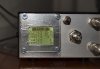
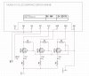
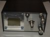
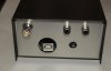
It is a project of building an LED driver dimming device ,
that will increase and decrease the output current of the drivers ,
within a certain-preset- period of time.
It works with drivers with 3IN1 dimming feature.

It has not much to do with the more advanced geo-location led controllers used in aquarium reef world.
In order to build something like those ,an external "clock" circuit / board has to be used along with a microcontroller ,so to provide a time base to the latter.

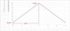
Still it mimics the Dawn-Noon-Dusk effect ... (DND for short )

The "AutosDias" device uses no external clock circuitry...
(It has pros' and cons',of course ... )

So ...
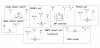
Let's move on to the basic Parts List :

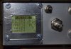
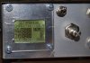
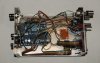
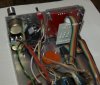
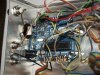
- 1x Arduino Uno microcontroller board
http://arduino.cc/en/Main/arduinoBoardUno
-1x "Nokia 5110" graphic LCD display
(the one with the red pcb ,not with blue pcb .Different pin out .)
https://www.sparkfun.com/products/10168
-1x 9-12 VDC power supply (wall plug type is fine )

- 2x Potentiometers 100K ,single turn ,linear


- 1 x potentiometer 10K multi-turn ,linear


-1 small single pole ,single throw switch


- 1 small button switch

-1 x 2 DIP switch


-Nx Case RCA female sockets .
( N =number of LED drivers controlled .Up to ~ 400 ...)
It has be the "case isolated " type,if they are going to be installed in metal casings .
The one with plastic isolating grommets/gaskets.


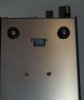
-1x Case to put all this inside/on ...
Approx dimensions : 100 mm wide x 150 mm deep x 50 mm high .


Other :
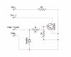
-1x 130 Ohm resistor .
-1x 1K resistor
-1x 2N3904 NPN transistor .


Optional :
1x 1N4004 diode
1x 1M resistor
6x 10K resistors
3x BS170 MOSFETs


And of course some wires ...
 
Last edited:

stardustsailor

Well-Known Member
Basic Operation :

The "AutosDias " device controls the LED driver(s) via PWM signaling.

The user adjusts / sets three parameters / variables.
- SMPR = Semi period
-BASE% = Lowest PWM duty cycle .
-PEAK% = Highest PWM duty cycle.

op.JPG
 
Last edited:

stardustsailor

Well-Known Member
I always thought that simulating dawn and dusk would just reduce yield in a 12/12 indoor set up. I've been using a 730 nm trigger at lights out and can run at 13.5/10.5 to increase my yields. Am I missing some info you could share?
Lots of info actually.
But let us be involved with that matter at the end of this thread.
I've opposite opinion of you .I THINK that actually simulating DND will INCREASE yields ,or
if not yields directly ,the yield efficiency of the system.
There's theories supporting and theories against .

My own is that we';re still 'missing' lots of info regarding energy and plants.
Energy =power x time.
You utilise 730 nm trigger at lights out and can run at 13.5/10.5 to increase your yields.
You put as much power and as much time ...
Plants are not machines like our led lights are.
They are living things like us.
We supply them with as much power ,while we think that they will handle or tolerate it ,
for 13.5 hours ..

(1500 umol/sec for 12 hours ....Where on Earth that is actually happening ?
Where are the experiment results that show to us that indeed ,blasting for 12 hours an mj plant with 1500umol/sec will make a monster yielding indoor plant ..? Or if the yields increase whatsoever ,are they worthy of the extra power and/or time of light ? )

While at the same time , plants themshelves 'show' us that usually within the same sun adapted species ,partially shaded plants have higher productivity /photosynthesis rates..
Ain't that odd ?
There's photoinhibition...Photosaturation ...Photo-respiration ...
Leaf angle is a good guide ...
Do you think that "praying" leaves at hour 01:00 since lights "ON" is a good thing ?
I say no ,it ain't ...
It shows that plants are already stressed from first hour of photosynthesis...
Let alone ,the rest 12 1/2 ...
Photosynthetic rates drop ..
Then yes,the extra one and a half hour is surely needed..:-)

Still ..alll these and plenty more is just theories ..
Actually,I've moved on to the experiment level ,by now ...
In a few months from now,I'll know for sure if simulating DND is worth it or not ..

Cheers.,
 
Last edited:

bicit

Well-Known Member
On the note of photo saturation, would a single dnd cycle over a 12 hour period actually be optimal? As opposed to say 12 dnd cycles per 12 hour period?

If photo saturation occurs within 1 hour then blasting them for 6 hours at 100% seems like it would be just as 'bad' as 12 hours.

Just curious about your theory, it sounds promising
 

stardustsailor

Well-Known Member
On the note of photo saturation, would a single dnd cycle over a 12 hour period actually be optimal? As opposed to say 12 dnd cycles per 12 hour period?

If photo saturation occurs within 1 hour then blasting them for 6 hours at 100% seems like it would be just as 'bad' as 12 hours.

Just curious about your theory, it sounds promising
Yes,you're right ...
:wink:
Later on ...
Let uf focus on the built first .
 
Last edited:

stardustsailor

Well-Known Member
Human Interface :

1) The multiturn pot sets the semiperiod (SMPR) .
It starts from 30 seconds (1/2 min ) ,up to 360 minutes ( 6 hours )

2) The two single turn pots ,adjust/set the BASE% & PEAK% duty cycle values.
In steps of 1% .From 0% up to 100% .

3) The small switch sets two operational modes : AUTO and SET/MANUAL .
PC312012.JPG

PC312013.JPG

4) The button-switch is RESET.

5) the 1x2 DIP switches divide- in four different settings- the 0-100 % range between the
BASE% pot and the PEAK% pot .

Setting A : BASE% pot : 0-19% PEAK% pot : 20-100%
Setting B : BASE% pot : 0-39% PEAK% pot : 40-100%
Setting C : BASE% pot : 0-59% PEAK% pot : 60-100%
Setting D : BASE% pot : 0-79% PEAK% pot : 80-100%
 
Last edited:

stardustsailor

Well-Known Member
LED DRIVER INTERFACE :
Caution: The led driver(s) used must be of the 3IN1 dimming kind.


driver interface.JPG

Optocouplers are too slow for PWM signals ...
Long story ...
BUT ...
Long live the transistors .

-One small NPN transistor ( 2N3904 ) used as PWM signal switch.

-The 1k res is the base resistor ,ensuring that transistor will saturate when "ON" .

-The 1N4004 diode is optional ,it protects from reverse voltage applied to PWM inputs.

-The 1M res is optional ,it ensures that the base of the transistor ( P type semiconductor) will be brought low
to ground.(transistor open ).If this res is not installed ,base of transistor is either "HIGH" or "FLOAT" and
not "HIGH" or "LOW".
Better be larger than 150 K.If not ,at 1-10% output power (+5VDC from microcontroller),
current may leak from microcontroller 's PWM output to PWM ground / DIM- and the drivers might even dim totally down to 0% of power !

_R2 is optional ,ensuring that DIM+ and DIM- will not just short ,when Duty Cycle = 100% .( +5 VDC from microcontroller).Refer to LED drivers spec sheet for actual value set .

Interface is inversing the PWM signal.

A "HIGH" signal from microcontroller ,closes the transistor ,and DIM+ & DIM- short .
This means 0% output power .

A " low " ( no signal ) from microcontroller ,opens the transistor ,
thus DIM+ and DIM- are open (unconnected) .
Output power is 100% .

Re-inverting the signal is done via software at the microcontroller level.
 
Last edited:

stardustsailor

Well-Known Member
I want to know how he finds the studies for his knowledge base, let alone the time to read them all, build luxury quality lights, AND work a full time job. SDS is superman.... or mr. Manhattan, haven't decided.
SDS has sailed through star dust oceans ,for so many times ,he does not even remember ..
Some say that SDS is even older than star dust itself.
So ,SDS ,had "all" the "time" in the ...universe.... to acquire some extra bits of knowledge ...


He misses some 'sleep' ,though ...
All this 'eternity' thing ,sometimes it just gets tiring enough ...

:wink:

Cheers.
:peace:
 

stardustsailor

Well-Known Member
CODE:
Along with Arduino IDE ,the two libraries needed are included in the zip file.

1)
Place the two libraries (folders Timer1 and LCD5110_3pin ) in the "Libraries" folder at the arduino IDE program installation folder.
2)
Upload at the Arduino Uno board the AutosDias.ino file.
 

Attachments

stardustsailor

Well-Known Member
Some pics of a complete "AutosDias" unit and few notes aside ...

1) Front side
PC312018.JPG
The LCD display ,protected with a piece of PMMA (=plexi-glass) .The three pots and the switch .
The switch used here ( double pole ) has a toggle OFF middle position (AUTO MODE ) and a toggle ON position (SET/MANUAL MODE) AND a "push-return single action " momentary ( ON ) position (lever moves at opposite side of toggle ON ) which is used for RESET .

( This switch is called ON-OFF-(ON) .
CAUTION : An (ON)-OFF-(ON) switch ,means that both poles are momentary ON=as long the switch is held manually ON.... )


2)Rear side PC312019.JPG Built to control two units.The BNC was installed for easier connection to an oscilloscope.
---With an BNC-RCA adapter ,the unit can control three light fixtures.----
3IN1 dimming feature ,usually involves a +10VDC power source at DIM+ pin of the led driver
and a current of 500uA ,when shorted with DIM - .
The transistor used (2N3904 ) as PWM switch , has a max Collector-Emitter current of 200 mA .
A single transistor then ,is able to control 200mA/500uA=400 drivers.
But ....
Still ,every pin of Arduino UNo can source (output ) only 40mA current at +5VDC.
(Hence the 130 ohm res at the pin 9 (pwm out) ,to limit the output current at ~40mA,thus protecting the pin from frying.)
40 mA /500uA = 80 led drivers.
A single Autos Dias unit can control up to ~80 led drivers featuring the 3in1 dimming system!

3)Bottom side.
PC312021.JPG
The DIP switches (only two of four connected ) setting / dividing the 0-100% duty cycle range between the two pots
( BASE% and PEAK% ) , into four presets .


4) inside #1
PC312014.JPG
Wire chaos!

5 ) inside #2
PC312015.JPG

Notice the MKT caps (grey things on pots ) used in every pot .connected to WIPER and GROUND pins of every pot.
Minimising noise & jitter .Ceramic caps can be used also.10-100 n is a fine range to choose a value from.

Check also LCD display adapter / MOSFET Logic Level Converter (grey pcb ).The 5110 lcd display accepts +3.3 VDC logic signals (data).Arduino UNO outputs +5VDC logic signals. A Logic Level converter has to be used to interface correctly those two devices.
More info and alternative solutions here :
https://learn.sparkfun.com/tutorials/graphic-lcd-hookup-guide

6 ) inside #3
PC312017.JPG
The 130 ohm resistor ,on a piece-of-art of output job ( :P just kiddin' ) .

Cheers.
:peace:
 

salmonetin

Well-Known Member
...:clap::clap::clap: control box add on... ...control box modular style... ...maybe with sensors and dataloging control box to monitoring not only the cobs, drivers or fans ...the temp or humidity on tent or exter to tent... levels for co2... ... or other functions... ...you know...i only dreaming...

saludos
 
Last edited:

stardustsailor

Well-Known Member
And a quick peek at the DND experiment site :

PC312028.JPG

The PWM ground (Arduino's ground ) and DIM- ,are common grounded (connected).
THEY MUST NOT BE COMMON GROUNDED WITH MAINS EARTH !
Here,the fixture's casing is earthed ,thus the RCA case socket used is the "case isolated" type.


PC312022.JPG
Four of them are 4-5 days old,since firstly emerged from ground.The rest two (middle ones) are younger by 2 days .
All of them regular Serious Seeds White Russian (one of my favourites ! Old schooler ..) .
All under 2x 3K-Ra80 Vero 29 COBs ,from start.

PC312023.JPG

And the current settings :
PC312027.JPG

Duty cycle starts at 10% to rise gradually up to 46% in ~15 min.
And then to drop back to 10% ,again in 15 min.
Two DND cycles per hour...x18 hours=- 36 DND cycles per day .

Plants seem to like it so far ...
.....Horizontally 'spread' wide open leaves ,I like too !!

Happy New Year!
Wishing to everyone ,for the best moments of 2014 ,to be the worst of 2015 .
See you next year !

Cheers.
:peace:
 
Last edited:

stardustsailor

Well-Known Member
And to clarify something :
I'm always using Photoshop at the pics.
Compress,Resize,Crop,white balance,sharpening,brightness adjust,shadows and contrast
are the ONLY " alterations" done(Most often being only crop and/or resize).
( Ok,sometimes I also "black cover" (hide ) " sensitive " parts of a scene ...)

Cheers.
 
Top