SSGrower
Well-Known Member
Wait a minute....Fuck this I gotta have a cob around here somewhere....
View attachment 4320927
I wanted a few 1750 mixed in on my rig, I sense a parts ordering frenzy.
Wait a minute....Fuck this I gotta have a cob around here somewhere....
View attachment 4320927
Wait a minute....
I wanted a few 1750 mixed in on my rig, I sense a parts ordering frenzy.
Not since they are epoxied, I remember what happened to the cobs I was looking for now.If you can, I'd test it on one of the COBs in your waterfall first. I'm not sure on how much power will/can be generated haha
I think it is safe to assume 1.2V @ 170ma per chip running at a junction temperature of 130F. How did I come to this number?If you can, I'd test it on one of the COBs in your waterfall first. I'm not sure on how much power will/can be generated haha
Good work. That's valuable data. I'd grab a measurement at 150f (?), maybe even higher (?), it could reduce the need for IR and increase peltier? Also, when the hot plate was ~125°, what was the heatsink peltier interface temp (as best you can)? Trying to determine gradient as best as possible. Lastly can you try blowing a fan at the setup from a distance in an effort to simulate a fan in a grow room used to circulate air (or did you use a 5v cpu fan)?I think it is safe to assume 1.2V @ 170ma per chip running at a junction temperature of 130F. How did I come to this number?
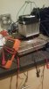
A hot plate stabilized at 120-130 peltier chiller or generator with heatsink and cpu fan running at 5v.
Measurements were as high as 2.2v @ 300ma for the chiller and 2.0v 240ma for the generator. The high readings on the chiller were right after I put it on the hot plate, the generator seemed to stabilize at higher voltage and current.
Given those numbers 1.2v 170ma nominal with a possible peak of 3v 400ma what red leds would fit?
At 20w, a 0.2w realization is only a 1% conversion rate with those particular devices and heatsinks used. Enough to charge an electrolytic for later use, and maybe some other uses too, most mid power 660nm are ~0.2w per chip (from what I've seen).I was able to measure a junction temp of 130F on a cx? 3070 running at 20 watts,
I don't see converting the voltage to be of much benifit due to additional losses.Good work. That's valuable data. I'd grab a measurement at 150f (?), maybe even higher (?), it could reduce the need for IR and increase peltier? Also, when the hot plate was ~125°, what was the heatsink peltier interface temp (as best you can)? Trying to determine gradient as best as possible. Lastly can you try blowing a fan at the setup from a distance in an effort to simulate a fan in a grow room used to circulate air (or did you use a 5v cpu fan)?
Given the .17A by 1.2V measurement, equating ~0.2w, you could maybe run (1) small 660nm, like an epistar 5730 but you'd want a few to make it worth the while I'd say. You can convert the V & I into whatever is needed, so the wattage or power is what is significant. At 0.2w not much added benefit that I see unless you have several. It would also depend on how many watts it takes to achieve such temps with the COB?
If it's only 0.2w, it could be used for UVB supplementation too. (2) could run (1) UVB chip. But 0.2w at 130f and a decent heatsink with a fan (?) is a little less than earth shattering lol but if it only takes 10w or less per COB to get that temperature it might be significant..
EDIT:
At 20w, a 0.2w realization is only a 1% conversion rate with those particular devices and heatsinks used. Enough to charge an electrolytic for later use, and maybe some other uses too, most mid power 660nm are ~0.2w per chip (from what I've seen).

I don't see converting the voltage to be of much benifit due to additional losses.
I was able to measure temps of about 70-80F on the backside of the heatsink, about 4mm thick aluminum 100W passive heatsink. So it was designed as a passive sink but what I found is without a fan blowing on it, voltage dropped below 1V very quickly. Not sure passive is the way to go here as they rely on a gradual temp gradient, the peltier needs a sharp diference.
Looking at the cxb3590 data sheet it does not even show luminus flux vs drive current for specific Tc for the low drive currents I use, but the different temp lines do converge and looks like between 55c and 85c you would loose myaybe up to 5% relative flux @ 700ma, I am running something like 300-500. If relative flux losses can be held to less than 0.5% due to the increased temp and a supplimental chip efficiency of >50% I feel like we could get ahead of the electrical losses via. generating a more compelete spectra. Thought these parameters my not be wholy quantifyable ie. the smoke is just better/worse.

After running this this thing again today I have some revised numbers. This time I let it sit in passive mode for over 3 hrs. Doing what I could to maintain the hotplate temperature at 190F as this seems to be the point where the peltier kicks it up a notch and stabilizes a bit. The plate temp was hard to keep constant, I think it will be much easier to do with an led and proper dimming driver.Ya that's what I was saying about a grow room fan. It might be enough air movement if you had a large enough passive to keep the cold side cool. When you stopped air flow the heatsink increased in temp and the gradient suffered so the power generation was less. Idk how big they make the heatsinks, what wattage, but you'd want the biggest bestest baddest one possible (I think), maybe even a 150w or 200w (if they make). If you have to wire a fan up to cool the Peltier enough to use it then it's actually counteracting your power generation. If you can use a source of air flow already present then you don't have to add in power to generate power.
After reviewing the cxb3590 data sheet, using a Peltier/seebeck is not going to increase maximum theoretical μmol/j, but they could still help you possibly achieve better than what you're getting now. If you look at the Tc° plots of "Current" vs "Relative Luminous Flux," you see about a 33% increase in current is needed to maintain intensity between the lowest Tc° data point and the highest Tc° data point, or between 25° and 105°. That's roughly a 33% increase in wattage for the same intensity, and if you only convert about 3% or 4% of the waste heat as electrical energy with the current technology, then it is more effecient to run the COB cooler and use 33% less power than try to recycle 3% or 4% of the heat. So its not going to increase industry μmol/j for COB but it could help you run a UVB supplemental or an FR initiator I think, and depending on your current operating temps. It is not going to increase effeciency better than keeping your chip cool.
View attachment 4321226
Idk, maybe it could help people with heat management issues by running a CPU fan (?), or power a small string of LEDs,.. of course depending on the seebeck devices used, power nessecity of LEDs, heatsink size, and air flow... Or at least it would seem.
On anther note, an OP amp current/voltage conversion cct might be able to achieve the electrical manipulation needed or at least that was my thinking.
EDIT:
- how well a guy can keep 1 side cool using passive heat control or without designed power addition
- the power generated vs "hot side" temp curve of the seebeck device
Heatsink size, & device selection... I think that's what it boils down to..
I should have realized the significance when you pointed that out earlier..Also notice where those graphs stop (1400 ma), I am running down at 3 - 400 and all the temp lines converge so chip temp differencs have less impact on effeciency.
What this is telling me (possibly lol)...At any rate after 3hrs of running in passive mode (IIRC it is rated at 100W passive) readings were 1.3v, 160ma, 187F plate temp, 139F backside of heatsink. At that point I turned the fan on and voltage immediately went up, by the time I got probe tips installed it was at 3.9 and falling, curent was over 300ma. It eventually stabilized at 2.35v, 293ma (0.688W !). I had to adjust the hotplate up cause the fan was cooling everything but once it stabilized at 190F the backside of the heatsink was 85F.
One thing that is way outside my comfort zone is designing a circuit to regulate and manage the power swings. I think of things like a current shunt or transistor switch to battery charger that runs the red leds at lights out. So maybe it looks something like a heasink with cob and peltier and some 1W chips driven at 50%, uv during day and red initiator at night


IIRC this is a 220 watt fixture? So you only need 224mw (at the wall) of uv to get a 10.6 uv index?Some thoughts on UV...
UV index...
View attachment 4323128
Wikipedia excerpt...
View attachment 4323127
https://en.m.wikipedia.org/wiki/Ultraviolet_index
When looking over what the UV index represents a few things stand out. The scale seems logarithmically weighted towards the shorter WV. 295nm is weighted at 100%, while 305nm only 22%, and 325 only a .3% weight. Refer to chart below...
View attachment 4323126
10mw/m2 = 1μw/cm2
So...
74mw (305nm) + .6mw (295nm)
=
~75mw/m2; ~7.5μw/cm2
It seems a midday summer afternoon could generate approximately 7.5μw/cm2 of UV from 295-305nm. That power UVB is representative of ~10.6 UV index. When referencing the UV index chart I notice 10.6 is actually a pretty high UV forecast, almost 11.
With the UV index weighted logarithmically I've pretty much disregarded 305nm+. With that in mind, it seems I only need to achieve ~7.5μw/cm2 of UVB to realize a relatively high UV index rating.
The light is designed for a 2'× 2', or for 3,716cm2. For the moment lets just assume that the UVB chips are lensed for 0 loss in stray emissions, ie every μw of UV reaches the 3,716cm2. That would equate to roughly ~28,000μw needed in total to cover the 3,716cm2. If the chips I'm looking at are able to produce between 2000μw - 6000μw at a peak of 295nm, an average of 4000μw can be utilized for a mean calculation, and I see that I would theoretically need ~7 chips to achieve a close equivalent of a 10.6 UV index. That's even at only a 1.25% effeciency in chip technology!(2.8mw/224mw)
Now granted I didn't include 325-305nm in the index measurement, I assumed complete light throw efficiency, and using an arbitrary set of values that I have no way of validating, also not sure what graph they are integrating to get the final value, but other than that its encouraging, lol idk, maybe I'm just trying to see what I want too..
Im not sure if the erythemal action spectrum (how much of what wavelength burns your skinn) can be exactly translated to a plant response. Skin and leaf is not the same. Also, @Randomblame was talking about having the right balance between uva and uvb. Apparently he had loss of yield with too much uvb.Some thoughts on UV...
UV index...
View attachment 4323128
Wikipedia excerpt...
View attachment 4323127
https://en.m.wikipedia.org/wiki/Ultraviolet_index
When looking over what the UV index represents a few things stand out. The scale seems logarithmically weighted towards the shorter WV. 295nm is weighted at 100%, while 305nm only 22%, and 325 only a .3% weight. Refer to chart below...
View attachment 4323126
10mw/m2 = 1μw/cm2
So...
74mw (305nm) + .6mw (295nm)
=
~75mw/m2; ~7.5μw/cm2
It seems a midday summer afternoon could generate approximately 7.5μw/cm2 of UV from 295-305nm. That power UVB is representative of ~10.6 UV index. When referencing the UV index chart I notice 10.6 is actually a pretty high UV forecast, almost 11.
With the UV index weighted logarithmically I've pretty much disregarded 305nm+. With that in mind, it seems I only need to achieve ~7.5μw/cm2 of UVB to realize a relatively high UV index rating.
The light is designed for a 2'× 2', or for 3,716cm2. For the moment lets just assume that the UVB chips are lensed for 0 loss in stray emissions, ie every μw of UV reaches the 3,716cm2. That would equate to roughly ~28,000μw needed in total to cover the 3,716cm2. If the chips I'm looking at are able to produce between 2000μw - 6000μw at a peak of 295nm, an average of 4000μw can be utilized for a mean calculation, and I see that I would theoretically need ~7 chips to achieve a close equivalent of a 10.6 UV index. That's even at only a 1.25% effeciency in chip technology!
Now granted I didn't include 325-305nm in the index measurement, I assumed complete light throw efficiency, and using an arbitrary set of values that I have no way of validating, also not sure what graph they are integrating to get the final value, but other than that its encouraging, lol idk, maybe I'm just trying to see what I want too..