Multichip LED, Remote Phosphor - Guess who it is.

Bumping Spheda

Well-Known Member
Idk why I don't take pictures while in the process, I just get in the zone and go too fast. BUT, I can explain the process and give you tips on disassembling a 9.5W Cree bulb if you're interested. I plan to mount the metal core PCB onto an Aluminum heat sink and using this in my veg tent.

gzli.jpg
So this what we're talking about (yours hasn't been taken apart... yet).
http://www.designingwithleds.com/cree-60w-led-replacement-bulb-review-and-tear-down/
I got this little tip here, but basically, preheat your oven to 200F and grab yourself some thick leather gloves to protect your hands. Place bulb in oven on a cookie sheet for 20 minutes. Take bulb out and grab the heat sink/base in one hand, and the silicone covered glass in the other. Now be careful because when I removed mine I pulled too hard and the heated glass sheared the protective covers off two of my LED's (you'll see in late photos). They still work, but Idk if I lost lumens on those two, or? So, what you wanna do, is pry the glass off (not twist), but just enough to crack the glue so that you can slowly pull the glass away from the rest of the assembly in a controlled manner.

1b0u.jpg
This is what you should see, but of course your LED's and PCB will still be in place. Pull the LED's off at this point and place somewhere safe, they're only being held on by friction. Careful, the metal may still be warm. Now, to get the heat sink separated from the base to get access to the driver there are three tabs (two have red arrows indicating their locations in the picture above), however, the glue that was holding the glass on is in the way (last red arrow in picture above). Get a knife and chip that stuff off/away from the clips. Once you do this you should be able to use the knife to pry those plastic tabs outwards and pull the heat sink off.

cymm.jpg
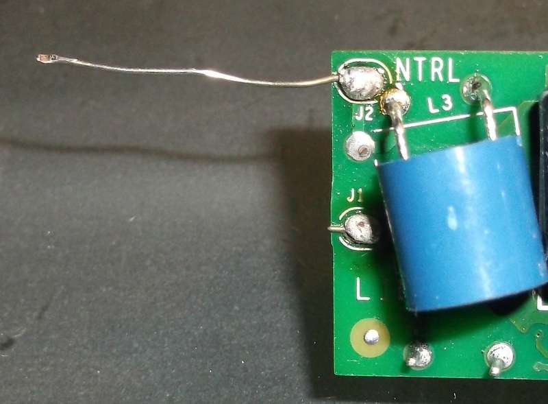
Look at the base. There should be a little wire hung outside. I took desoldering braid and desoldered the wire so I could pull the base off. Pretty easy, not much is holding it on so you should be able to do this by hand.

a3oz.jpg
Now you can pull the driver out. On both the driver and the LED PCB there are designated tabs for (+) and (-) so you can't mess it up.

yrt5.jpg19zq.jpg2hqd.jpg
Get a set of needle nose pliers (or two) and bend the PCB as flat as possible. Notice the two LED's second from the left in the second pic? Hum, sliced those suckers right off. :3 Anyway, I soldered wire with molex plugs onto each set of tabs so I can quickly (dis)connect the heat sink/LED's from the driver if I ever have to. Both the driver and LED PCB's have (+) and (-) clearly labeled so it'd be hard to mess up. I'm going to find a power cord for the driver, solder that on (no polarity, remember) and then spray a couple coats of PlastiDip over the driver. I really don't want things shorting out on me at any time and fudging things up. If you have a small box that it would fit in (a LARGE pill case, maybe?) I say drill holes in it, feed all the wires through and solder that puppy up.

0m39.jpg 71j.jpg
What size heat sink should I buy? Well, it measures ~65mm x ~32mm, so something larger than that I'd say.
http://cgi.ebay.com/ws/eBayISAPI.dll?ViewItem&item=200800824597&ssPageName=ADME:L:OC:US:3160
That's what I just bought. I was waiting to measure the PCB before I bought anything so there wasn't a face palm moment later on. Yeah, it's on the large side, I could have saved a few bucks, I know. I liked the height of the fins, and... Idk. Buy whatever looks good to you. Judging by the size of the stock heat sink if the new heat sink is large enough for the LED PCB to fit completely on it should be large enough.


Well that wraps things up pretty much. Waiting for the heat sink and I'll probably have an update for you guys on this build within the next week or so. Hope you enjoyed it.
 

Bumping Spheda

Well-Known Member
Insulating/closing your compressor slots on the sides and top of a regular window AC will fry the unit fast. What you wanted was a pass- thru-wall unit where it only exhausts heat out the back (which can and effectively be removed by your box^^}and cost way more $$$ due to this design. Even in its intended use you want zero obstruction within two feet of the regular window unit outdoors.

not trying to be a wise ass, just don't want you burning up a brand new AC!I know you don't want the compressor contributing heat to the room(like the portable ones, guess why they have the compressor slots open?:-P ) but remove the the top and side insulation == just insulate/exhaust the heat out the back coils only!

Unless you have a through-wall AC......then I wrote this shit for nothing;-)

Yes i'm on my phone......hence the crappy sentence structure....
Hey, no offense taken. Since you're on your phone I'm not sure if you can see, but the intakes for the condensing coil are NOT covered up. The top intake is 100% uninhibited and the two side intakes have 1-2" before there's a wall or tent constricting airflow. This should be enough, imo. Let me know what you think.

BUT, just so things are clear, the insulated box that I tacked onto the back of the AC unit is ONLY redirecting the AC's exhaust off the back coil into my attic. Everything else is left stock.
 

PSUAGRO.

Well-Known Member
Hey, no offense taken. Since you're on your phone I'm not sure if you can see, but the intakes for the condensing coil are NOT covered up. The top intake is 100% uninhibited and the two side intakes have 1-2" before there's a wall or tent constricting airflow. This should be enough, imo. Let me know what you think.

BUT, just so things are clear, the insulated box that I tacked onto the back of the AC unit is ONLY redirecting the AC's exhaust off the back coil into my attic. Everything else is left stock.

Ah I get it ....... well now maybe next time I'll look on a fucking proper screen before chirping in!:-P ha.....anyways nice diy and disassembly of the cree bulb, cool shit brother. I thought someone in Franjan's thread said the diffuser globes can be removed with just force and no heat/plastic softening was needed??
 

Bumping Spheda

Well-Known Member
No harm, no foul. If I had NOT known about the workings of AC units you'd have been a Godsend.

As for the Cree mod, thanks! I tried to remove the glass with no heat but wasn't that lucky, I guess. I wouldn't doubt that it can be done, however. Perhaps there's a technique? Pretty sure I was still trying to twist the glass at that point, I think wiggling the glass up and down is better. Either way, heat or no heat, I'd still wear gloves in case the glass cracked. Those would be some nasty cuts if done with bare hands. Then again, you could just crack the glass on purpose and remove it that way. Idk what I'll be doing with my globe, I've got no real use for it...
 

Fholston

Member
Hi PetFlora,

Where'd you buy your tubes? I'm looking to add some supplemental light to some plants I'll be flowering soon. Can you help in directing me to some good LED tubes?
 

SnotBoogie

Well-Known Member
"Chips on board", its just a multichip on a flat pcb :)

Hello everyone by the way, haven't forgot about ya :D just hyper busy at the moment. Grow got aborted by the heatwave while i was away for a couple days. so sad as it was about 2 and a half weeks before ready. :(

Peace :bigjoint:
 

Bumping Spheda

Well-Known Member
"Chips on board", its just a multichip on a flat pcb :)

Hello everyone by the way, haven't forgot about ya :D just hyper busy at the moment. Grow got aborted by the heatwave while i was away for a couple days. so sad as it was about 2 and a half weeks before ready. :(

Peace :bigjoint:
Hey, man, no worries, I've been gone for a month! Glad you stopped by. Sorry to hear about the heat, I'm dealing with a similar issue myself, so I know what that must have been like. D:

Interesting how they use 'standard' chips in these T8's. I wonder why they don't state the size of the chip, though. I'd like to see 45x45 chips advertised, but most of these manufacturers just state "COB." Maybe we'll see "performance" LED tubes in the near future.
:fire:
 

PetFlora

Well-Known Member
If you are going to use tubes...consider using the 'COB' type.

http://www.aliexpress.com/item/1-2M-19W-T8-COB-TUBE-CLEAR-COVER-100-FACTORY-MANUFACTUR-FREE-SHIPPING/689402334.html

Better and more uniform light then the 5050 diodes used in other tubes...

Been looking at COB tubes as an alternative, but the flat panels are more flexible (and simpler) to implement, and eliminates the cheap/cheezy tombstones. The company making the flat panels sent me specs, but I was unable to open the file. I requested a different file but haven't gotten it yet

The problem with buying direct is quantity. I have been trying to get 2700K tubes to finish my girls under for a couple weeks (too late now). No one in US seems to have them, unless I am willing to pay ~ $60/tube + shipping. Shipping a couple tubes from China > $40, extra fee due to 4ft+ considered 'over-sized'.

I would need to order 10+ tubes (typical min, often 50 pieces) to spread the fee, but all I need is a couple (2-4) for flower


Bumping Spheda

Well-Known Member
iq.jpg

~3rd week into flower. Didn't write the date down when I flipped her so even I don't know how far along she is. Her leaves in some areas are folding downward in half, and there's still quite a bit of tip curl. She looks pretty hideous from some angles, I won't lie, but in this shot she looks pretty good, imo. There's just too many bud sites for me to take pictures of. I go back to look at them and just get lost, I'm like, "Wait, didn't I just see these?" So this will have to suffice.

Kinda lackluster, imo, I'm hoping she really packs on the weight some how.

And still no sign of the heat sink for the Cree's. I'll post an update as soon as that project's finished along with another tour of the veg room.

-Edit-
Ah, fuck it. What a boring post. Here's a few more.
8rdn.jpgk646.jpgn7uu.jpg
 

FranJan

Well-Known Member
Hey BP, here's the pix from my problem area. I can't figure out how to pull the base off without cutting at least one wire. That's some small ass soldering one has to do to get the AC attached :). Maybe it's better to leave the base on and run it in one of those E27 to AC adapters? IDK. This is the part where, to me at least, it's just not worth the hassle when you can get a 10x3 XP-E array and driver delivered to your house for 20 bucks or less. I noticed that you shaved a few of the diodes from that one pic like I did. That's what I mean about being tough to work with, like I said in captainmorgan's thread. Still great post and I'd rep ya again if I could.


And I think if one goes with COBs that you're better off waiting till their efficacy goes up or at least get the beam angle set to 90° or even 60° if you're gonna flower with them. The thing about COBs is that they're an array of smaller diodes packed together tightly, or as tight as cooling allows, to take advantage of the efficacy/efficiency of smaller diodes, so cooling seems to be paramount, so use high CRI COBs to have some leeway with cooling, especially since their spectrums are most likely less than optimal. Or at least that's how I see it :).
 

FranJan

Well-Known Member
Haha, actually I just figured out how to do it while puffing on some high CBD Jack H, so :confused:bongsmilie:eyesmoke::!::mrgreen: LOL. Tin-Snips kiddies. Carefully snip the nipple off and that wire should survive.

Still getting those suckers perfectly flat is the challenge also.
 

Bumping Spheda

Well-Known Member
Those pictures broke my internet Fran, I'm glad you got it sussed out on your own! Sounds like you sheared the center pin off the Edison base and took the second internal wire with it. I just yanked the base off with my hands the wire stayed connected to the driver.

As far as COB's go, I'm not sure I follow you. AFAIK larger chips tend to be more efficient. The advantage of COB's, imo, is large chip size (make sure to buy the right ones), more ideal thermal path, low cost, and ease of setup. Also, you mention spectrum, efficiency/efficacy. The COB light I'm using for flower is mostly Blue (45W 440nm, 45W 470nm I believe for broader Royal Blue coverage) and it's behind an Intematix Remote Phosphor lens. The Blue chips aren't Cree, or anything, but it's still a 90 Watt, 90CRI, 2700k COB light with 10W of 660nm built in (custom spectrum ordered from VanQ). Given the design issues I had this ended up running me more than I expected, but it's still a good light if you ask me (sort of yet to be seen, let's wait for this Chiesel to finish). Also, one kind of cool thing to mention is that I've got the window AC blower pumping into my flower tent via a 4" duct and I just propped the duct right in front of the CPU cooler fan intake. I've literally got chilled air running through my heat sink fins. :hump:

Also, have you seen the new Magnum panels? Now, granted they don't have the fancy parabolic reflector, but I've already seen tons of Chinese stuff built extremely similar to those (member heckler73 owns one, pictures are within this thread). I believe LED panels will naturally progress to multiple ~50W COB's for the next generation, and we're already seeing this sort of thing happening (VanQ's series of panels, the new line of Magnums, the Diamond series panels using Cree COB's as White supplementation, Kessil H150 knockoffs from ?HGL?, etc). I'm waiting for selectively phosphor coated COB's and higher end chips. With time.
 

PetFlora

Well-Known Member
BS, be careful directly cooling the heat sinks, a few inches above, no problem, but directly through could cause diodes to struggle to reach nominal temps. Maybe I'm overreacting, but... like you said it cost more than you anticipated

Well, the 2 x 2 panels I'm getting are 45w distributed uniformly over the entire area, so no hot spots, per say (very COB like). I am confident this is the way to go after watching my girls under 4 @ 20w x 4 ft led tubes.

Basically, each plant is under a 15 x 15 area (~24w directly above each) where diodes have 120 lens angle. I plan to move the 2 x 2 bulb shop light fixtures near the upper part of the side walls and hang the 2 @ 45w panels above the canopy. Probably eliminate the need for under canopy globes. 175wv 110 should help make for bigger PHATer nuggz
 

FranJan

Well-Known Member
Dude they ain't that big. LOL

And as you increase die size, the larger the emitter gets the greater it's ability is to absorb light is, so it becomes less efficient at generating light. Also increasing current lowers efficacy. I'd cut and paste something from my books but they're all on my tablet, which isn't here ATM but the Lenks in "Practical Lighting Designs With LEDs" give many good examples of this including how 2 diodes running at lower mA can put out just as much light as 1 diode running at a higher mA, resulting in better efficacy. Small diodes are easier to cool too, at least for now.

And from what I've seen, the XMLs that Advanced uses aren't COBs, they're older model CREE SMD arrays, still better than most but I have no idea what they run them at. Magnum uses SMD arrays too from what I gather, and are probably the better choices for both than COBs. I saw Vanq's COBs but didn't see any of their panels using them, just arrays. Makes me see a pattern ;).

And how in the hell did you pull the base off with your hands???? And not pull the wire from the driver?????? You must have the hands of a surgeon or the luck of the Irish :smile:.


Hope you don't mind me dumping this here BS. It's some reading for all the folks out there that might want some of this SMD/COB shit straightened out. And yes PetFlora you can start screaming about MCOBs now ;).

http://www.ledaladdin.com/light_guides/LED_Lighting_Evolution.html


Comparison And Differences Between LED Technologies: DIP vs. SMD vs. COB vs. MCOB
http://hitlights.com/blog/comparison-and-differences-between-led-technologies-dip-vs-smd-vs-cob-vs-mcob/www.

Choosing an LED technology is like choosing the right winter coat to wear: there are different models that provide more or less features depending on what you might need. Once you decide the features you want from your LED, you can easily choose the package type accordingly. The “package type” refers to the way an LED’s semiconductor die–similar to the filament in an incandescent–is *packaged inside LED devices for different applications. The LED package can be very basic, like with the DIP LEDs, or it can be very versatile to handle lots of different needs, such as with the SMD package. Modern LED technology as we know it was developed in 1962 by Nick Holonyak with his invention of the DIP LED, and the LED industry has been innovating it ever since. The following article is meant to be a brief overview of the major types of LED package technology that are commercially available today.

[HR][/HR]
Dual In-Line Package LED technology has been around for more than 50 years, and is likely what you think of when you picture an LED. Though it is old, DIP LEDs are far from outdated as they are still used extensively today for large signs and displays. The widespread use of DIP LEDs came about due to their long life-span and intense brightness. DIP LEDs are highly recognizable by their “pill” or “bullet” shaped design (≤5mm wide), and the long contacts that extend from the bottom of the LED which can be easily soldered or inserted into a bread board. The LED’s plastic and epoxy casing actually serves as a lens that can focus the light coming from the diode. The shape of the outer casing also includes a flat edge on one side that always indicates the cathode side of DIP LEDs.

These lights, when used for residential or home use, are typically found in electronics as indicator lights because of their low cost, high brightness, and ease of install. DIP Diodes can be bought in bulk by electronics manufacturers to fulfill many purposes; and because of their plug-and-play nature, can be easily soldered to any kind of circuit board. This gives electronic devices the ability to send information to the user without the need for an actual display on the device.

These LEDs will typically produce between 3 and 4 lumens per LED. They typically run at between 5v to 24v, with 12v being the most common voltage. They individually pull between 0.05 and 0.08 watts. This generates between 35 and 80 lumens per watt, depending on the actual LED.
[HR][/HR]
The SMD chips, or “Surface Mounted Device” chips, have become very popular due to their versatility. SMD LEDs have been used to create everything from light bulbs to strip lights, and even missed call indicators on cell phones. These chips are much smaller in comparison to the DIP technology, which tends to give them the added versatility over DIP diodes. SMD technology also supports chips with more complicated designs, such as SMD 5050 chips (depicted to the left), that have RGB capabilities on a single chip. This is very powerful for color combinations, as opposed to the DIP technology, which can only display one color per device. The technology does not take the bullet shaped design from DIP LEDs, and is closer to that of a flat, square computer chip. It is also worth noting that SMD chips can have more than just two contacts (one anode and one cathode). SMD chips can have 2, 4 or 6 contacts, depending on the number of diodes on the chip. With the SMD design, there is an individual circuit for each diode. For example, SMD 5050 chips have 3 diodes on the chip, which translates to 3 circuits and a total of 6 contacts.

SMD chips have been a very important development for the LED industry because of the ability to put 3 diodes on the same chip. When a chip includes a red, green, and blue diode, you have a chip that can create any color you want by adjusting the level of output from each individual diode on the chip. Because they are very bright and can change colors, these chips are used extensively for LED strip lights and light bulbs. SMD LED chips come in a wide variety of sizes, the most common of which are SMD 3528 and SMD 5050S. SMD 3528 chips are only 3.5mm wide, and SMD 5050 chips are 5 mm wide. SMD LEDs can also be made much smaller than the 3528 and 5050 chips. Some of these chips are made very small, to go in high end electronics such as cell phones and laptop computers as indicator lights. Any cell phone you see that has a little light that stays on after the screen turns off is powered by a small SMD LED.

SMD chips that we see in light bulbs and strip lights will typically produce between 4 to 5 lumens per diode on a chip (such as a 3528, single diode chip). These chips will typically run at either 12v or 24v, with 12v being the most common. Individually these chips can pull between 0.05w to 0.08w (single diode, 3528) up to between 0.15w to .24w (three diode, 5050). This means these chips can produce between 50 and 100 lumens per watt depending on the particular chip.
[HR][/HR]
The most recent LED development has been “Chip On Board” or COB technology. COB and SMD can be similar because like SMD, COB chips have multiple diodes on the same “wafer” or chip. However, this is where the similarities end. In fact, on every COB chip there are multiple diodes; typically 9 or more. The other big difference between COB and SMD technology lies in the fact that while SMD requires a circuit for every diode included on the chip, COB devices only have 1 circuit and 2 contacts for the entire chip regardless of the number of diodes. This single circuit design, regardless of the number of diodes on the chip, leads to simplicity for the rest of any COB LED device. Perhaps even more important than the simplicity aspect, COB also leads to improved lumen-per-watt ratios in comparison to other LED technologies such as DIP and SMD. Unfortunately, the big draw back from the single circuit design of COB chips stems from the fact that multiple channels are necessary to adjust individual levels of light output to create color changing effects. What this basically means is that COB technology, while very powerful and efficient in single-color applications, cannot be used to create color changing bulbs or lights.

Before COB technology, LED spot lights and flood lights were historically considered “non-standard lamps” because they required multiple LED sources to produce a high lumen output. Since the advent of COB chips in the LED arena, a large lumen count can be produced from a single source using a COB chip. This was never possible before COB, but has been a revolution for people who want to lower their energy bill but also need a standard lamp. Besides spot lights and floodlights, COB chips have been put into all kinds of bulbs and used for a number of other applications as well. In fact, COB technology is used for any small device with a flash such as a Smartphone or camera. The principle is that COB chips produces a large amount of lumens for very little energy, which is very important for any device that runs on a battery. Many Smartphones have a small 2×2 or 3×3 COB matrix to produce their camera flash. Point-and-shoot cameras similarly support a small COB chip that will use little energy and produce a large amount of light.

COB chips vary widely in their applications and thus different chips will require different wattage, voltage, and will produce vastly different lumen counts. However, it can be said of COB chips that the ratio of lumens per watt is very high, typically 80 lumens per watt minimum to well over 1oo lumen per watt.
[HR][/HR]
Since the creation of COB chips, a variant has come along called MCOB or “Multiple Chip On Board”. MCOB devices are very similar to COB chips in their application and are more or less just multiple COB chips together in series. MCOB devices differ from COB because they are better for low wattage situations. They also do not fulfill the standard lamp requirement for spot light and floodlights, as mentioned earlier in the COB section of this post. While MCOB devices do not meet the requirements to become a standard lamp, they produce a lot of light and are great for low wattage situations like A19 bulbs. In fact, A19 bulbs are currently the most common use of MCOB technology. If you buy an LED A19 bulb in the near future, it will likely be an MCOB bulb.

MCOB is a very new technology at this point that not many manufacturers are producing, but it will likely catch on for much more than just A19 bulbs. There are many applications for a high lumen count that MCOB can fulfill, and likely innovators will use the technology to create new products that the market has never seen before. The world of LED lighting is exciting when we see that it is changing and evolving right before our eyes. Soon we may have yet another technology that is a contender in the LED market!
 

Chronikool

Well-Known Member
Very good Fran.... :)

It seemz that the single COB is doing the roundz for populairty in household bulbs....(at least in my shitty research...) much easier to implement for the manufacturers at the moment i guess...and much cheaper for the cheapest fuck head around.... :)

IMG_5933.jpgIMG_5932.jpgIMG_5935.jpg
 

Bumping Spheda

Well-Known Member
Fran:
"Large" chip size for me is 42mil Reds and 45mil Blues. That's what's in my COB. Also, you say larger chips absorb more light. Why not use whatever the best size chip is for the blue portion, selectively coat that with phosphor, and then use whatever size chips you want for the rest of the COB? And how do other LED technlogies circumvent this better than COB's do? And, similarly, couldn't you run multiple COB's at lower current and achieve the same efficacy?

VanQ's panels that I was talking about:
http://www.vanqled.com/ledgrowlight/index.asp?bigclassid=52&class=245

Magnum:
http://www.357magled.com/G2-PARmaxx-Parabolic-450w-LED-Grow-Light_p_19.html
Those aren't 50W COB's?

Not sure what the difference is between an "array" and COB. You're right about the Diamond series, but the rest of this stuff looks like a bunch of COB's to me. I'm not sure if we're speaking the same language, though. You say wait for COB's to reach 90 degree viewing angle. Why?
 
Top