LED DIY : " Extreme Measures "

stardustsailor

Well-Known Member
This is a thread ,that it's aim is to collect/ gather all sorts of "exreme measures" ,meaning
all the craziest ideas to deal with common -technical- problems ,regardingDIY led growing and DIY led panel building ...

Everybody is welcome to post ,all sorts of thoughts regarding , of theoritical or practical solutions ....
 

stardustsailor

Well-Known Member
I 'll make a start .....

Sometimes, either accidently , when building a led grow panel or/and normally ,
during usage -only for "bare-leds" ,uncovered led panels-,
hard silicone lenses of leds ,may get " dull " ,impairing somewhat the light output
(due to diffusion & internal reflections )...


Some/most ? ceramic leds have a -protective-" lens " or " encapsulant " as referred in led -jargon,made out of Hard Silicone ....

New- " uncontaminated " silicone encapsulants are transparent and with a highly glossy / lustrous / shinny outer surfaces ....

Due to it's "rubbery " nature ,this silicone material ,if accidently touched with bare hands (especially if greasy-dirty ...) ,skin will
degrade the highly glossy / lustrous / shinny outer surface of the lens .....

Same thing will happen by usage in dirty & moist environments ,with air -currents .... (i.e inside a growtent ) ...
Lens will become "dull" by time ,if exposed for prolonged periods of time ....


Can it be fixed ?


Well ,officially ...No....
There is not such an "application note " or guide .....

But ,I've found a way .....
Not tested for long time ,but up till now it works just fine .....
Time will tell .....

Fixing a "dull " hard silicone led encapsulant .

Tools / Materials needed :

-Soft,high quality , natural hair paint brush ....
Smallest number/size ..As tiny tip as possible ....

-Distilled Water

-IPA (IsoPropyl Alcohol )

-Silicone Lubricant
(Spray can ,most common container .Used to renew and protect ,
automobile plastic interior/exterior parts ,bike suspension O-rings,etc .
Used also to water -proof tents ,pants ,jackets,etc . )

-Small container (i.e. a bottle cap )

Steps :

1-Wet the brush tip with distilled water ....Static goes ....
2- Dip the brush tip in IPA .
3- Pre-clean the led lens ,carefully & thoroughly ,with the brush and plenty of IPA ..
4-Let the lens dry .
...
5-Spray a tad of Silicone Lubricant in the small container .Just a tad ...
6- Let the "propeller gas" to evaporate.Wait 20" .
7-Dip brush in water .Static goes -if any -....
8-Dip brush in lubricant ...Wipe excess lub ,from brush tip ...
9-Wipe softly led lens with Silicone Lubricant ....Softly ....

That was all ....

Silicone lubricants are chemically inert , they do not conduct electricity ,
do not change color or corrode/dissolve led materials ,
do not mess with "heat-path " or cooling ,
they do not burn up up to ~500°C ,they do not dry or solidify ,they leave no residues ...
And they possess anti-static properties ...

Tested . Works fine .
Dull lenses look like new again and stay like that ....
P5156560.JPG.....Ready ...Set ..Go ....
P5156561.JPG<=.....dirty lens....
P5156562.JPG<= ....cleaning with IPA ....
P5156563.JPG<=.....Cleaned with IPA ,dried ,but dull ....(black residues are from extra dirty brush used .. !!! )
P5156564.JPG<= After silicone lub treatment ....Like new ,(fried up die---- :-P )led !! !
 

RainerRocks

Active Member
SDS

I bought Lenses for my LED's so I been reading many forums on how to attache to LED.

I read not to use crazy glue because after a while it will leave a film /fog from fumes on the LED and lens.

See post #6..I have read this on many forums not just this one.
http://www.reefcentral.com/forums/showthread.php?t=2046022

Also here in red it says not to use glue.
http://www.ledgroupbuy.com/cree-led-optics-lens/

So as of now I haven't installed the lenses on the LED's. Still haven't decided on
what to use but I will not be using glue.


Do you know anything about this ?
 

stardustsailor

Well-Known Member
SDS

I bought Lenses for my LED's so I been reading many forums on how to attache to LED.

I read not to use crazy glue because after a while it will leave a film /fog from fumes on the LED and lens.

See post #6..I have read this on many forums not just this one.
http://www.reefcentral.com/forums/showthread.php?t=2046022

Also here in red it says not to use glue.
http://www.ledgroupbuy.com/cree-led-optics-lens/

So as of now I haven't installed the lenses on the LED's. Still haven't decided on
what to use but I will not be using glue.


Do you know anything about this ?
Yes ..In fact fumes from cyanoacrylate resin (super glue ) ,
often react with moisture, forming a hard whittish opaque film ...
In fact ....
This Super glue's property ,was used once upon a time by foresincs ,in order to take "subtle traces " of fingerprints ,in certain situations ....

!!! -NEVER,BUT NEVER , USE SUPER -GLUE (CYANOACRYLATES ) AT ANY CASE ,WHEN WORKING WITH LEDS.

........NEVER !!!


I'd use a high quality soft silicone glue ...
It can come -off easily (relatively ) ,also -if needed so ...
Heat resistant .Does not affect/melt/dissolve pcb -lens polymer -leds ...
Easy to use . can be formed/trimmed/shaped with soapy wet fingers,before harden .
 

SnotBoogie

Well-Known Member
One of my most cowboy techniques - on the spot fixing of a bad solder joint, in-situ, without turning off LEDs so the HS was warmer. Yes i actually plugged my iron in my tent and got on my back underneath (braving drops of hot solder LOL). :dunce:


We should also talk about inclined mounting surfaces ( this ^ shape) for spectral mixing. It would seem to me, this is the most theoretically effective way to mix? since you can literally overlap the light output of each "half" of the panel. I have a kinda similar thing going on by accident in my tent at the moment.
 

Rasser

Active Member
Hi, I haven't been on this forum since last year so maybe you got this covered but just in case.

It felt like extreme measures the other day when I was repairing my busted 120W UFO for the 2nd time,
the first time I removed all the screws witch even with a powered screwdriver took forever,
so when it broke for the second time i was out of patience and got ruff and just cut the lens off and removed the plastic
around the LED, soldered the gap in the metal plate beneath and it worked as a short-circuit.

The hard part was to locate the broken LED, witch I did by using a very tiny metal needle in the space between
the LED and the pcb to probe the voltage.


Chronikool

Well-Known Member
Hi, I haven't been on this forum since last year so maybe you got this covered but just in case.

It felt like extreme measures the other day when I was repairing my busted 120W UFO for the 2nd time,
the first time I removed all the screws witch even with a powered screwdriver took forever,
so when it broke for the second time i was out of patience and got ruff and just cut the lens off and removed the plastic
around the LED, soldered the gap in the metal plate beneath and it worked as a short-circuit.

The hard part was to locate the broken LED, witch I did by using a very tiny metal needle in the space between
the LED and the pcb to probe the voltage.


I think i just saw a ghost! :)

Good to have you back Rasser! :)
 

stardustsailor

Well-Known Member
In order to proper reflow tiny ceramic leds (Cree-Osram-Philips-etc ) and have a good result ,
solder paste has to be applied with the use of a stencil .....

Here's some tips / ideas ....

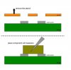
Proper -professional grade solder paste stencils are :
-laser cut ,
-at a trapezoid profile of ~5° ........ ( / _____ \ ) ......
-and with circular corners in pad design / cut ...
-Made of stainless stell sheet
( thickness varies depending led : from ~100 um to 150 um .120um suggested for most leds ) ...
....
s sten 1.jpg.....


If there's a company around ,that uses laser to make signs, metal decoration parts ,etc,
Make in Photoshop a led solder pad ,according to manufacturer's recommendations (found on leds spec pdfs ) ,at real size ,
and have your stencil professional grade made,for small amount of $ ....


Another way is to go and purchase from an Art's shop ,some copper foils/sheets ... (cheap ) ...
Used for artistic copper etchings ....

(Can you imagine ? " M.C. Escher Printed Circuit Boards Company LTD " .... :eyesmoke:..... )


You can find them in plenty of available thicknesses ..( ~50 um to ~ 250 um or more .... ) .....


Make a leds's pad design with Photoshop ..
( Tools like -Rectangular shape -Smooth/Sharpen edges -fill -Invert ,might come handy ...)
In it's real dimensions at designing & printing sizing .....

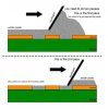
Print it with laser printer ..And thermally transfer it onto copper foil/sheet ..
(background : toner full -pads : plain paper /empty )

Use packing tape to cover the rest of copper foil ...
Back ,sides,everywhere except on the print .
Make 100% sure that you've made a water-proof job !
Tape has to be firmly stuck with copper foil ...


Etch the thing ....

Now ,you have your own stencil ...

Thing is that it can not be used many times ..

It is made out of soft copper and will deform by time ,as several stencils will be made ...
Then you just have to make another ,new one ,same way ....


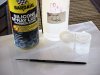
-Apply solder paste immediatly when taken out from fridge ..
(Solder paste is stored for up to 6 months in fridge .)
The colder (thick -hard-solid) the paste ,the more clean and accurate it will sit / stay,
after applied and stencil is removed ..

Working with such tiny apertures and warm solder paste ,can drive you crazy !
Trust me on that ....


-Cut a strip from an old cash / phone / credit card to use as a solder paste spreader ,over the stencil .
...0.5- 1 cm wide is nice ....
With some fine sandpaper ,work-softly/gentle- the edge ,to make it smooth ,without abnormalities and totally straight ..

-place/glue fine grain ( > #1000 ) sandpaper on a flat board and move/work the strip on the sandpaper .
Not the sandpaper over a still hand held or viced ,credit card strip -

A good,stiff ,flat ,smooth " spade " / " spreader " is crucial ....


-Get some fine tattoo needles ...!!!
Perfect for hand re-working/ trimming applied solder paste..
Clean the "gaps" between connections ,remove excess paste ,etc ..


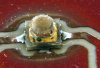
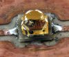
-Use _grounded preferably _ a pair of tweezers to place the leds over the solder paste "pads " ....
Light handed ....Reallllyyyy gently ....
Just drop them ...
Do not "plant" them ,with force ....

Drop them over solder ,as close to their right position as possible .

Lightly push the leds at side of case ,with tweezer tip,to "trim" them in place ....

While reflowing ,solder will self-align the leds ....
align.jpg...


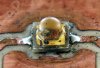
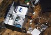
-Using a hot plate / stove plate to reflow leds ,once done couple of times starts to be fun and a piece of cake ....
In fact it is way easier than manually done ,hand soldering with a solder gun ....

You will start to reflow everything ,afterwards ....Solder gun will collect dust !

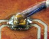
All the secret lies on solder paste stencil ....
Applied Solder paste,at pcb pad , has to be at right thickness ,even ,flat ,with no gaps / voids and precise .
If done correctly (delicate job,not difficult ! ) ,a close to perfect home-made reflowing is almost 100% guaranteed ....


-My personal approach in stencil applying is this :

a ) I work / " pass over " several times with the spreader per led .
Not just once .

stnc 1.JPG...=> stnc 2.JPG
I use a small amount of cold solder paste ,placed in a small blob ,directly on the copper
stencil foil ,near the led pad "voids" of stencil ...
Then with the plastic card spreader,I work it from several directions ,until i get a good
filled ,flat and smooth solder stencil ....Then I remove the copper stencil /mask and move to the next led's pads ..

b ) I tend to use a "solo " led stencil strip ....
Not the whole array of leds printed on one single stencil sheet...
Difficult to place ,align and hold still ,while placing solder paste in many leds .....

So I use a thin strip ,with a single led pad stencil close on it's one tip end ....

It can be used for replacing single (fried) leds from a led array ....

Yes ,kinda slow work ,working each led stencil one by one ,
but it bewcomes rewarding ,while reflowing ....
 

stardustsailor

Well-Known Member
Soon ,I 'llbe building my very own reflow station ...
-And maybe post a "DIY guide ,about it ...-

Anyway ...
It's is going to be Arduino based ,with advanced and calibrated " Proportional-Integral-Derivative -aka PID " temperature control ,
so to match the solder profile of solder used ...

..
Now I'm gathering the parts for the first part of the reflow station ...

"The brain" part....
The " PID control unit "

(complete with 12 V power supply for Arduino ,25A Solid State relay ,mains socket for output ,
16 A fuses pre/post relay ,16 digit LCD screen ,etc .....)

P5316615.JPG...


The other part -"the muscle" one - is going to be either a 'specially hacked' small oven(" reflow oven " ) ,
or a special built with stove round ceramic heating elements (" hot -plate ")....
(Both can be 'driven' ,by the " PID control unit " ! )

Time for some serious ,pro-grade ,led soldering .....
 

stardustsailor

Well-Known Member
Some links about the project all over my table ....

- http://www.kukata86.com/en/what-is-reflow-oven-controller ( <= Arduino Shield for reflow soldering )

- http://www.rocketscream.com/shop/reflow-oven-controller-shield-arduino-compatible ( <= Arduino Shield for reflow soldering )


- http://www.negtronics.com/simplot ( <=great plotting tool .
Reads serial port data-send by Arduino - and plots 'em ..Kinda of oscilloscope ...)

- http://learn.adafruit.com/thermocouple/ (<==thermocouple info )

- http://www.avrfreaks.net/index.php?name=PNphpBB2&file=viewtopic&p=934103 (<= nice topic,lots of info ... )

- http://www.beta-estore.com/rkuk/order_product_details.html?wg=1&p=242 (<===Reflow Control PID unit ....)

- http://www.instructables.com/id/DIY-Soldering-Reflow-Oven/ (<= DIY... adventures ... )

- http://hobbybotics.com/projects/hobbybotics-reflow-controller-v8-03/ ( <== This guy iz amazing ! ! ! )
 

tekdc911

Well-Known Member
my problem is space the area needed to put enough led's to get a crazy bumper crop
even if i only got a few watts extra from each panel/light when you add it all up it would be like having an extra light almost
 

stardustsailor

Well-Known Member
.....After " mastering " the arts of custom mcpcb -ims etching & Solder paste ' stenciling',one brave LED DIYer & grower has to master
the art of reflow soldering .....

But which type & equipment of reflow soldering suits led soldering ?

Experience ,personally ,has showed me ,that nothin' beats HOT-PLATING .


.................................

Also :

Reflow equipment

Basic methods for reflow

There are four heating modes involved with SMT reflow processes: conduction, latent heat, infrared radiation (IR) and convection.
Heat transfer by conduction occurs when two solid masses at different temperature are in contact, and within the same mass if a temperature differential exists within it. Reflow systems using conduction include:


  • Hot-plate reflow, now used mostly for solder paste evaluation and applicable only to boards which conduct heat well (such as single-sided assemblies on ceramic substrates...Or HIGH PoWER LED mcpcbs / IMSs ..I might add ...).
  • As a hand process, it suffers from lack of control and a tendency to shake the crystallising solder joint!
  • With a series of hot plates, over which the product is carried on a thin belt, this becomes &#8216;belt reflow&#8217;. For improved conduction, the function of the belt is sometimes replaced by a series of board &#8216;pushers&#8217; moved by a chain
  • The so called &#8216;hot bar&#8217;, which applies a heated tool to the pads to be soldered: frequently this is a square annulus in shape. Heat may be provided by a conventional element (as with a soldering iron) or with a combined tool/heater fed by a welding power supply.
All these are relatively small-scale processes, and only the last can be applied to SM assemblies on a PCB, where &#8216;hot bar&#8217; soldering is occasionally used for rework or for the assembly of large complex devices.
Latent heat of evaporation is the heat which is absorbed by a fluid when it turns into vapour and released when the vapour recondenses. This mode is used by the &#8216;condensation soldering&#8217; process.
Radiation: infrared (IR) radiation is emitted by all bodies and heat transfer occurs whenever two bodies at different temperatures are in sight of each other. IR is a non-contact heat transfer process that was used in the earliest designs of reflow oven, but now coexists with, and has mostly been replaced by, convection heating.
These last three methods of heat transfer can be implemented at all levels upwards from low-volume batch systems. The sections that follow concentrate on convection (the main runner for larger users) and on high-volume flow-line systems, where a tight level of process control needs to be exercised.

http://www.ami.ac.uk/courses/topics/0132_rs/

So ....

Dealing with the first disadvantage of method .....

lack of control......
 
Top