DIY: Cree CXA Arduino Thermal Monitoring & Protection.

stardustsailor

Well-Known Member
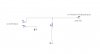
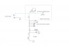
A relatively simple to make ( and relatively cheap ) thermal monitoring and protection system ,
for the range of CXA led arrays ...
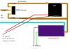
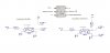
This microcontroller based automated system ,can monitor and protect real-time ,up
to six CXA arrays .Thus all the analog inputs ( A0-A5 ) of the Arduino Uno are being used .
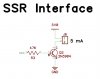
And one digital output (Pin 5) for the Solid State Relay ,which will power off the led drivers (at their AC line )
if needed .

Parts :

-Arduino Uno Rev.3
-1x Solid State Relay(SSR) Normally Open or Normally Closed . Dc 3-32 V / Ac 110-240 V 50-60 Hz,5-25 A depending of the led drivers total power
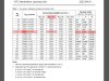
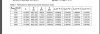
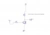
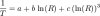
-6x NTC (Negative Temperature Coefficient ) tiny sized thermistors 10K ,1-3%
-6x 10 K resistors
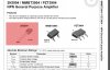
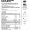
- 1x 2N3904 transistor +1x 47 K + 1x 4.7 K or 10K resistors
or
- 1x 4N33 optocoupler + 1x 4.7K or 10K + 1x 1 or 2.2 K resistors
-Arctic Silver Thermal Epoxy,or any other Silver nanoparticle loaded thermal epoxy.

-(optional for the filtered version input:
-7x 100nF ceramic capaitors
-1x 47uF /16V/108°C electrolytic cap
- 1x 10-22uH inductor
-1x 10 Ohm resistor )


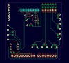
-(optional) DIY perforated pcb /arduino blank -project shield,for placing the circuit..
- (optional) 12 V 1000mA PSU for the arduino..
-(optional) 5V linear power supply ,for 'clean' Voltage Reference .
-(optional) 1x 2x 8 or 2x 16 LCD display for the Arduino
(Code for display will be added also )
 
Last edited:

stardustsailor

Well-Known Member
The Arduino Code :

/* ********************************Arduino Thermal Monitor & Protection For Cree CXA Led Chip on Board Arrays************
/ by StarDustSailor 2014
*/
//PINS LAYOUT
#define SSR_PIN 5 // SOLID STATE RELAY OUTPUT PIN 5
#define SENSORA_PIN A0 // SENSOR INPUTS
#define SENSORB_PIN A1
#define SENSORC_PIN A2
#define SENSORD_PIN A3
#define SENSORE_PIN A4
#define SENSORF_PIN A5
//USER DEFINED VARIABLES
#define THR_NOM_RES 10000 // NOM.RES OF THERMISTORS
#define TEMP_NOM 25 // NOM TEMP. OF NOM. RES :-)
#define B_COEF 3977 // B COEFFICIENT VALUE
#define SAMPLE 5 // SAMPLES FOR AVERAGING
#define SER_RES_A 10000 // SERIES RES OF SENSORS VOLT DIVIDERS
#define SER_RES_B 10000 // BETTER ACCURACY IS OBTAINED ,IF
#define SER_RES_C 10000 // THE EXACT VALUE OF EACH 10K RESISTORS IS MEASURED
#define SER_RES_D 10000 // AND THE VALUE IS CHANGED HERE.DEFAULT IS 10K =10000
#define SER_RES_E 10000
#define SER_RES_F 10000
//INT
int samplesA[SAMPLE];
int samplesB[SAMPLE];
int samplesC[SAMPLE];
int samplesD[SAMPLE];
int samplesE[SAMPLE];
int samplesF[SAMPLE];
//SET UP
void setup()
{
Serial.begin(9600);
pinMode( SSR_PIN,OUTPUT );
digitalWrite(SSR_PIN,LOW);
pinMode (SENSORA_PIN,INPUT);
pinMode (SENSORB_PIN,INPUT);
pinMode (SENSORC_PIN,INPUT);
pinMode (SENSORD_PIN,INPUT);
pinMode (SENSORE_PIN,INPUT);
pinMode (SENSORF_PIN,INPUT);
}
void loop()
{
uint8_t i;
float averageA;
float averageB;
float averageC;
float averageD;
float averageE;
float averageF;
for (i=0; i< SAMPLE; i++)
{
samplesA = analogRead(SENSORA_PIN);
samplesB = analogRead(SENSORB_PIN);
samplesC = analogRead(SENSORC_PIN);
samplesD = analogRead(SENSORD_PIN);
samplesE = analogRead(SENSORE_PIN);
samplesF = analogRead(SENSORF_PIN);
delay(10);
}
averageA=0;
averageB=0;
averageC=0;
averageD=0;
averageE=0;
averageF=0;
for (i=0; i< SAMPLE; i++)
{
averageA += samplesA;
averageB += samplesB;
averageC += samplesC;
averageD += samplesD;
averageE += samplesE;
averageF += samplesF;
}
averageA /= SAMPLE;
averageB /= SAMPLE;
averageC /= SAMPLE;
averageD /= SAMPLE;
averageE /= SAMPLE;
averageF /= SAMPLE;
//
averageA = 1023 / averageA - 1;
averageA = SER_RES_A / averageA;
//
averageB = 1023 / averageB - 1;
averageB = SER_RES_B / averageB;
//
averageC = 1023 / averageC - 1;
averageC = SER_RES_C / averageC;
//
averageD = 1023 / averageD - 1;
averageD = SER_RES_D / averageD;
//
averageE = 1023 / averageE - 1;
averageE = SER_RES_E / averageE;
//
averageF = 1023 / averageF - 1;
averageF = SER_RES_F / averageF;
//
float TCA;
TCA = averageA / THR_NOM_RES;
TCA = log(TCA);
TCA /= B_COEF;
TCA += 1.0 / (TEMP_NOM + 273.15);
TCA = 1.0 / TCA;
TCA -= 273.15;

float TCB;
TCB = averageB / THR_NOM_RES;
TCB = log(TCB);
TCB /= B_COEF;
TCB += 1.0 / (TEMP_NOM + 273.15);
TCB = 1.0 / TCB;
TCB -= 273.15;
float TCC;
TCC = averageC / THR_NOM_RES;
TCC = log(TCC);
TCC /= B_COEF;
TCC += 1.0 / (TEMP_NOM + 273.15);
TCC = 1.0 / TCC;
TCC -= 273.15;

float TCD;
TCD = averageD / THR_NOM_RES;
TCD = log(TCD);
TCD /= B_COEF;
TCD += 1.0 / (TEMP_NOM + 273.15);
TCD = 1.0 / TCD;
TCD -= 273.15;
float TCE;
TCE = averageE / THR_NOM_RES;
TCE = log(TCE);
TCE /= B_COEF;
TCE += 1.0 / (TEMP_NOM + 273.15);
TCE = 1.0 / TCE;
TCE -= 273.15;
float TCF;
TCF = averageF / THR_NOM_RES;
TCF = log(TCF);
TCF /= B_COEF;
TCF += 1.0 / (TEMP_NOM + 273.15);
TCF = 1.0 / TCF;
TCF -= 273.15;
//SERIAL SCREEN (SET TO 9600 BAUD )
Serial.print("CXA#1 Tcase : ");
Serial.print(TCA);
Serial.println(" °C");
Serial.print("CXA#2 Tcase : ");
Serial.print(TCB);
Serial.println(" °C");
Serial.print("CXA#3 Tcase : ");
Serial.print(TCC);
Serial.println(" °C");
Serial.print("CXA#4 Tcase : ");
Serial.print(TCD);
Serial.println(" °C");
Serial.print("CXA#5 Tcase : ");
Serial.print(TCE);
Serial.println(" °C");
Serial.print("CXA#6 Tcase : ");
Serial.print(TCF);
Serial.println(" °C");

//
// SOLID STATE RELAY PROTECTION RULES
if ( TCA >= 93|| TCB >= 93||TCC >= 93|| TCD >= 93|| TCE >= 93||TCF >= 93)// 93C is set limit
{
digitalWrite(SSR_PIN,HIGH);
}
else
if ( TCA < 93&& TCB< 93 &&TCC< 93&& TCD< 93&& TCE < 93&&TCF < 93)
{
digitalWrite(SSR_PIN,LOW);// CHANGE TO HIGH IF IN TRANSISTOR CONFIG .
}

delay(500); // SET TO 1000 FOR SLOWER , MORE STABLE OPERATION.
}
//END


...for some reason ,while the code is working fine ,when i copy-paste from RIU ,I
get a weird message at Arduino's software ..
Can anybody help on that ?
Why Copying-Pasting the code from RIU ,makes the code not to work ?


Last edited:

stardustsailor

Well-Known Member
The Input circuit . ( the six sensors ) to the Arduino .

A ) Simple Version ( but can be noisy ,thus more inaccurate )

simple.JPG

For each sensor ,copy the circuit.

The 10 K resistor is called the "Series Resistor " in the voltage Divider circuit here ...
For getting the 5V ,you can use either the +5V power pin of Arduino or an external +5V ...
( an old mobile phone's battery charger for example ...)
At second case you have to connect the ground of the 5VDC psu with the Arduino's one ..
(Common Ground Device Connection ).

For better accuracy ,measure each of the six 10K series resistors ,note the measures down for each resistor ,and at the arduino code change the red part ..

#define SER_RES_A 10000
#define SER_RES_B 10000
#define SER_RES_C 10000
#define SER_RES_D 10000
#define SER_RES_E 10000
#define SER_RES_F 10000
Example:
If you measured one to be 9.450 Ohms ,and it is going to be used for the second CXA array ...
Change " #define SER_RES_B 10000 " to " #define SER_RES_B 9450 "


B ) Filtered Version ( Low Pass filter + jitter damping )
At this input version ,one small 10-22 uH inductor ,one 100nF ceramic Cap ,one 10 Ohm resistor
and one 47 uF /16V electrolytic capacitor are needed ,to make A low-pass filter at the +5VDC
line ...It cleans from ripple noise ,the power line,so it won't affect readings .

For every sensor a 100n ceramic cap is needed to bypass and dampen jitter noise .
filtered.JPG As before ,measure each 10K series res ,and change the values accordingly to the code ,for higher precision.
 
Last edited:

stardustsailor

Well-Known Member
The sensors .
NTC : Negative Temp .Coefficient ....
Thermistors are special resistors made out of semiconductor material (yes ,like leds ) and the
NTC ones ,as the temperature rises ,they lower their resistance ..,.

For this monitoring/protection system we 'll need tiny NTC 10K thermistors ...
At 25°C they have a nom.resistance of 10000 ohm .

The ones I found on the local market ,are made from Philips with part number :

2322-640-6-6103.....

After some web searching ...

search 1.JPG
And some more searching ....

search 2.JPG


search 3.JPG
Now ....This is a parameter needed ...The B coefficient Value ...
At this case is 3977

To Arduino Code :#define B_COEF 3977 // B COEFFICIENT VALUE

Change this number ,depending on the thermistors you 're going to use .
Look up for it ,at the thermistors datasheet .

If you find something like that :

numbers to keep.JPG


Note the A1 ,B1 ,C1 and D1 ones ...
( as they are really ..For example ,for my case ,A1= 0.003353832 ,B1= 0.0002569355,etc ...)
Soon ,another Arduino code ,utilising them .is coming up ,for you to choose which one you like best ..
(probably the second one -using those numbers in the math equations- is going to be even more precise ...)
Later on,I haven't written anything yet ..It's still on my mind ...The code ...


Thermistors are sensitive passive devices ...Be careful how you handle them ...Be gentle ..

You 'll need the Silver particle Epoxy ,to glue them at the Tc copper pad of the CXA array ...
Make sure ,that they contact the pad ,flat-wise and then apply just a small blob of epoxy ,
to cover the thermistor from top .Let the epoxy flow towards the array pad .
Try to keep a clean contact between the thermistor and the pad ,without any epoxy in between ...Epoxy should just "engulf ' the thermistor ,and let flow towards the array pad to bond there ...
Wear latex or vinyl gloves ,ground your selves to avoid any ESD to the CXA ,and be gentle ..

Cover with epoxy any naked part of the thermistor pins .
 
Last edited:

stardustsailor

Well-Known Member
The Output....
Now ..
Things tend to be a tad complicated here ...
And mainly because of individual personal preferences or.... restrictions ....( Yeah,why not ? )

The Pin 5 (output for the SSR at code ) of the Arduino is a digital pin ...
It means that it outputs either HIGH or LOW ..
0 or 1 ....
When " HIGH " the pin outputs ~ 5V DC ..( 4.9x to be exact ..)
When "LOW " the pin is pulled down at Ground . 0 V ...

At code :

// SOLID STATE RELAY PROTECTION RULES
if ( TCA >= 93|| TCB >= 93||TCC >= 93|| TCD >= 93|| TCE >= 93||TCF >= 93)
{
digitalWrite(SSR_PIN,HIGH);
}
else
if ( TCA < 93&&TCB< 93 &&TCC< 93&&TCD< 93&& TCE < 93&&TCF < 93)
{
digitalWrite(SSR_PIN,LOW);
}
What is says here ^^^^^?
Well it says ,that if ANY ( || : OR ) of the case temperatures are detected to be 93°C or higher ,then
Arduino will pull up Pin 5 to it's high state ...Pin 5 will be outputting 5 Volts ,if one ,two or all of them ,the T case
values rise to 93 ° C or above ...

If again
ALL ( && :AND) of them are below 93 C ,then the pin 5 will go LOW ..( 0V )
 
Last edited:

stardustsailor

Well-Known Member
IF we reverse the HIGH into LOW and the LOW into HIGH :
i
f ( TCA >= 93|| TCB >= 93||TCC >= 93|| TCD >= 93|| TCE >= 93||TCF >= 93)
{
digitalWrite(SSR_PIN,LOW);
}
else
if ( TCA < 93&& TCB< 93 &&TCC< 93&& TCD< 93&&TCE < 93&&TCF < 93)
{
digitalWrite(SSR_PIN,HIGH);
}
!!!! And change this line also,at Set -Up string !!! :
void setup()
{
Serial.begin(115200);
pinMode( SSR_PIN,OUTPUT );
digitalWrite(SSR_PIN,HIGH); <= at code is LOW by default
Then Arduino will behave opposite now...

Pin 5 will continuously be HIGH ( +5V ) and if any TC of any CXA chip goes 93 C or higher ,the Pin 5 goes low and outputs zero ...( GND ) ...
Same that all TC have to be below 93 C ,for Pin 5 to go high again ...
 

stardustsailor

Well-Known Member
Why we 've to know the above ?

Well firstly it depends from the type of SSR used and secondly the way (allowances vs restrictions ) one
wants to use the thermal protection via SSR ...


Two types of Solid State Relays exist ,regarding hoew they operate ...

1) the first type is the most common in use ,the NO type .
Normally Open type.
That means ,that as long as no DC signal ( 3-32 Volts usually ) is applie to the DC side of the SSR ,the AC
side remains open ...No AC current pass through the SSR ...

That means that the SSR has to have A constant DC signal in order to stay at Closed state
and thus allow AC to pass ,in order for the CC led drivers to Switch on.

That means also ,that if that signal ,for any reason is lost ,the CXAs will switch off ,as the SSR will return to its
" Normal State " which is Open ...

If that signal comes directly from Arduino and Arduino fails, the SSR will go open .
IF that signal comes from another power source ( a small 5 volt ,500mA mobile phone charger ,for example ) ,it
depends from the output circuitry in between Arduino and the SSR ,what will happen .
We can have it either the CXAs to go off ,or either to stay on ,without any thermal protection ,since Arduino has failed ,
but the SSR remains closed ,cause it receives a dc signal from other source ,than Arduino ...

It all comes down to personal preferences or the LED light fixture's allowances or restrictions
present or bewished ..
 

stardustsailor

Well-Known Member
In the most probable case ,of using an NO SSR ,it will be wise to set a SPDT switch ( Single Pole ,Double Throw )
before the SSR unit ,in order to have the 'SSR bypassing' option..
No matter of the output circuit and the operational way chosen ,it is a relay with a normal state "OFF"
and it will be wise to have a bypassing way...

bypassing switch.jpg
 

stardustsailor

Well-Known Member
The second type is the NC type .
Normally closed .
At this case no bypassing switch is needed ,because the SSR at it's normal state ,behaves
as it is not there ! It lets AC current pass through.
If a DC signal is applied then the SSR will cut off the AC power to the led drivers ..

With this type of SSR ,if anything goes wrong ,it depends exclusively at the Arduinos output circuit ,
what will happen next and
in order to stay open it needs an external PSU ,if Arduino fails ...
 
Last edited:

stardustsailor

Well-Known Member
Output Circuits :

This small circuitry placed is between Pin 5 of Arduino and the SSR..
And they are of two operational types and of two connection types ...

For the operational part there is the " Buffer " circuit and the " Inverter " circuit ...

For the connection part there's the "Common Ground " and the "Isolated " ones ...

Let's see them ...

Buffer means that a HIGH signal from PIN 5 is transmitted as a HIGH to the SSR ...
Buffer : HIGH=>HIGH , LOW=LOW
Inverter means that a HIGH signal from PIN 5 is transmitted as a LOW to the SSR ...
And the LOW from pin 5 ,is inverted to HIGH and transmitted to SSR
Inverter: HIGH=> LOW ,LOW=HIGH

Now ..Imagine the combos

Pin 5 can either continuously be HIGH ,and if CXA overheat be LOW ..
Or the opposite
Pin 5 can either continuously be LOW ,and if CXA overheat be HIGH ..

That is set at code ..( Software buffering/ Inverting )

And then Output circuitry that can transmit the same signal state or invert it
(hardware buffering/Inverting )

And then is the two types of SSR ..Normally Open vs NormallyClosed..

Each combo that you can imagine/make has it's own unique pros'n'cons ,
regarding operation and thermal protection in normal
or in case of Fault/Fail conditions of the Monitoring/Protecting System .

Will analyse them ..
Give me some time..
( And your love,of course ...)
 

stardustsailor

Well-Known Member
But first let us see the circuits one by one ...
Let's start with the "Common Ground " ones


Common Ground Buffer ( CGB ) output circuit :
Parts : -1 x 2N3904 NPN transistor + 1x 47 K resistor

2N3904.JPG
Take note of the Emitter-Base-Collector pins of the (most common ) TO-92 package ..


SSR transistor buffer.JPG


Just solder a 47K resistor at the base of transistor (middle pin ) ..
The other end of the transistor goes to Pin 5 ..

Emitter pin of the transistor goes to Ground (-)
Collector connects to Cathode of the SSR ...
Anode of the SSR is supplied directly with the +5Volt .
(either from arduino's power pin ,or you set an unused pin as output at set up and set as high *)

*At the code add :
(...)
//PINS LAYOUT
#define SSR_PIN 5 // SOLID STATE RELAY OUTPUT PIN 5
#define SENSORA_PIN A0 // SENSOR INPUTS
#define SENSORB_PIN A1
#define SENSORC_PIN A2
#define SENSORD_PIN A3
#define SENSORE_PIN A4
#define SENSORF_PIN A5
#define EXTRA_PWR_PIN 8
(...)
......
(...)
//SET UP
void setup()
{
Serial.begin(9600);
pinMode( SSR_PIN,OUTPUT );
digitalWrite(SSR_PIN,LOW);
pinMode (SENSORA_PIN,INPUT);
pinMode (SENSORB_PIN,INPUT);
pinMode (SENSORC_PIN,INPUT);
pinMode (SENSORD_PIN,INPUT);
pinMode (SENSORE_PIN,INPUT);
pinMode (SENSORF_PIN,INPUT);
pinMode ( EXTRA_PWR_PIN,OUTPUT);
digitalWrite( EXTRA_PWR_PIN,HIGH);

}
(...)
....
With this added code, pin 8 now outputs +5V and can source 200mA max ...
Only ~5mA are needed for the SSR DC signal ...
Pin 8 can be used as a +5 V power source for the SSR signal of the "Common Ground Buffer "
If another external source is used to provide those +5V for the SSR signal ,then the GND of Arduino and the external PSU ,have to be connected together (common Ground )

Also there is common ground between arduino and the DC part of the SSR ...

How the circuit works :
Simple ! As a switch !

When pin 5 is high ,current passes through the 47K res to the base of the transistor ,thus
opening the Collector -Emitter way and thus current flows to the SSR .
(NPN transistor :Negative input -Collector - Positive Base -Negative output -Emitter- )

Arduino PIN 5 HIGH => NO SSR will close (and power the led drivers on )
Arduino PIN 5 LOW => NO SSR will open (and power off the led drivers )

Arduino PIN 5 HIGH=> NC SSR will open (and power off the led drivers )
Arduino PIN 5 LOW=> NC SSR will close(and power on the led drivers )


At this case we set through software at which case (Normal CXA operation or Overheat Faulty Condition ),
pin will be HIGH or LOW ,depending of the SSR type .
 

stardustsailor

Well-Known Member
Common Ground Inverter ( CGI ) output circuit :
Parts : -1 x 2N3904 NPN transistor + 1x 47 K resistor+1x 4.7 K resistor

Arduino PIN 5 HIGH =>LOW at NO SSR will open (and power the led drivers off )
Arduino PIN 5 LOW => HIGH at NO SSR will close (and power on the led drivers )

Arduino PIN 5 HIGH=>LOW at NC SSR will close (and power on the led drivers )
Arduino PIN 5 LOW=> HIGH at NC SSR will open (and power off the led drivers )


SSR transistor inverter.JPG


How it works :
If pin 5 is Low ,then no current goes to the base of the transistor ..
The transistor is open and the Collector -Emitter do not contact current.
From the +5 V source ,through the 4.7 K res*
current flows to the anode of the SSR .Pin 5 is LOW ,but output to the SSR is HIGH (+5V ) ..

(*althought you can do the circuit without that resistor in some cases ,better have it there ..
It 'limits' the current flowing ,from the +5V source,to the inverter's output,so that the SSR will not receive any 'signal' ,when transistor contacts ...
In some cases even-depending on the SSR's input sensitivity ,
it might be better to increase to 10K ,as some SSRs need very low DC currents as signal
and the 4.7 K might not be enough to prevent current 'leaking' to SSR ... )


If pin 5 is High ,then current flows to the base ,and the transistor contacts .
The current now flows from+5V to ground through the transistor and no current goes to the SSR..
Pin 5 is HIGH ,but output to the SSR is LOW (0V ) ..

( Cathode / - of the SSR is directly connected to -LOL- 'common' Ground )
 
Last edited:

stardustsailor

Well-Known Member
The code based on the Extended Steinhart-Hart Equation:

// Arduino CXA3070 Silistor/ Thermistor Thermal Monitor & Overheat Protection
//2014 SDS
//BASED ON the Extended STEINHART-HART EQUATION
// 1/T= A1+B1* ln (R/Rref) +C1 *ln^2 (R/Rref)+D1 *ln^3 (R/Rref)
//LIB.
#include <math.h>

//Pins
#define SSR_PIN 5
#define SENSOR30A_PIN A0
#define SENSOR30B_PIN A1
#define SENSOR50A_PIN A2
#define SENSOR50B_PIN A3
#define SENSOR27A_PIN A4
#define SENSOR27B_PIN A5
//VAR
#define THR_NOM_RES 10000
#define TEMP_NOM 25
#define AI 0.003353832
#define B1 0.0002569355
#define C1 0.000002626311
#define D1 0.000000675278

#define SAMPLE 5
#define SER_RES_30A 10000
#define SER_RES_30B 10000
#define SER_RES_50A 10000
#define SER_RES_50B 10000
#define SER_RES_27A 10000
#define SER_RES_27B 10000
//INT
int samples30A[SAMPLE];
int samples30B[SAMPLE];
int samples50A[SAMPLE];
int samples50B[SAMPLE];
int samples27A[SAMPLE];
int samples27B[SAMPLE];
//SET UP
void setup()
{
Serial.begin(115200);
pinMode( SSR_PIN,OUTPUT );
digitalWrite(SSR_PIN,LOW);
pinMode (SENSOR30A_PIN,INPUT);
pinMode (SENSOR30B_PIN,INPUT);
pinMode (SENSOR50A_PIN,INPUT);
pinMode (SENSOR50B_PIN,INPUT);
pinMode (SENSOR27A_PIN,INPUT);
pinMode (SENSOR27B_PIN,INPUT);

}

void loop()
{
uint8_t i;
float average30A;
float average30B;
float average50A;
float average50B;
float average27A;
float average27B;
for (i=0; i< SAMPLE; i++)
{
samples30A = analogRead(SENSOR30A_PIN);
samples30B = analogRead(SENSOR30B_PIN);
samples50A = analogRead(SENSOR50A_PIN);
samples50B = analogRead(SENSOR50B_PIN);
samples27A = analogRead(SENSOR27A_PIN);
samples27B = analogRead(SENSOR27B_PIN);
delay(10);
}
average30A=0;
average30B=0;
average50A=0;
average50B=0;
average27A=0;
average27B=0;
for (i=0; i< SAMPLE; i++)
{
average30A += samples30A;
average30B += samples30B;
average50A += samples50A;
average50B += samples50B;
average27A += samples27A;
average27B += samples27B;
}
average30A /= SAMPLE;
average30B /= SAMPLE;
average50A /= SAMPLE;
average50B /= SAMPLE;
average27A /= SAMPLE;
average27B /= SAMPLE;
//
average30A = 1023 / average30A - 1;
average30A = SER_RES_30A / average30A;
//
average30B = 1023 / average30B - 1;
average30B = SER_RES_30B / average30B;
//
average50A = 1023 / average50A - 1;
average50A = SER_RES_50A / average50A;
//
average50B = 1023 / average50B - 1;
average50B = SER_RES_50B / average50B;
//
average27A = 1023 / average27A - 1;
average27A = SER_RES_27A / average27A;
//
average27B = 1023 / average27B - 1;
average27B = SER_RES_27B / average27B;
//
float TC30A;
TC30A = average30A / THR_NOM_RES;
TC30A = log(TC30A);
TC30A =1/(AI+(B1*TC30A)+(C1*TC30A*TC30A)+(D1*TC30A*TC30A*TC30A));
TC30A =TC30A- 273.15;
float TC30B;
TC30B = average30B / THR_NOM_RES;
TC30B = log(TC30B);
TC30B =1/(AI+(B1*TC30B)+(C1*TC30B*TC30B)+(D1*TC30B*TC30B*TC30B));
TC30B =TC30B- 273.15;
float TC50A;
TC50A = average50A / THR_NOM_RES;
TC50A = log(TC50A);
TC50A =1/(AI+(B1*TC50A)+(C1*TC50A*TC50A)+(D1*TC50A*TC50A*TC50A));
TC50A =TC50A- 273.15;
float TC50B;
TC50B = average50B / THR_NOM_RES;
TC50B = log(TC50B);
TC50B =1/(AI+(B1*TC50B)+(C1*TC50B*TC50B)+(D1*TC50B*TC50B*TC50B));
TC50B =TC50B- 273.15;
float TC27A;
TC27A = average27A / THR_NOM_RES;
TC27A = log(TC27A);
TC27A =1/(AI+(B1*TC27A)+(C1*TC27A*TC27A)+(D1*TC27A*TC27A*TC27A));
TC27A =TC27A- 273.15;
float TC27B;
TC27B = average27B / THR_NOM_RES;
TC27B = log(TC27B);
TC27B =1/(AI+(B1*TC27B)+(C1*TC27B*TC27B)+(D1*TC27B*TC27B*TC27B));
TC27B =TC27B- 273.15;
//SERIAL SCREEN (SET TO 115200 BAUD )
Serial.print("CXA#1 Tcase : ");
Serial.print(TC30A);
Serial.println(" °C");
Serial.print("CXA#2 Tcase : ");
Serial.print(TC30B);
Serial.println(" °C");
Serial.print("CXA#3 Tcase : ");
Serial.print(TC50A);
Serial.println(" °C");
Serial.print("CXA#4 Tcase : ");
Serial.print(TC50B);
Serial.println(" °C");
Serial.print("CXA#5 Tcase : ");
Serial.print(TC27A);
Serial.println(" °C");
Serial.print("CXA#6 Tcase : ");
Serial.print(TC27B);
Serial.println(" °C");

//
if ( TC30A >= 90|| TC30B >= 90||TC50A >= 90|| TC50B >= 90|| TC27A >= 90||TC27B >= 90)
{
digitalWrite(SSR_PIN,HIGH);
}
else
if ( TC30A < 90&& TC30B< 90 &&TC50A< 90&& TC50B< 90&& TC27A < 90&&TC27B < 90)
{
digitalWrite(SSR_PIN,LOW);
}

delay(1000);
}
//END

This code is a much better than the previous.
The measurements are more presice.
But to use it ,you have to know the
A1 ( or A ) , B1 ( or B ) ,C1 and D1 ( used as C* ) of the thermistor you 're using .
Check the manufacturer's datasheets .
extended steinhart-hart.JPG

* the Extended Steinhart-Hart equation is :

extended steinhart-hart 1.JPG

While on Wiki :
b38d29f9f9bfc793911f56069f96e0c5.png
http://en.wikipedia.org/wiki/Thermistor

^^^this one is the simplified version ...
.......

The Steinhart–Hart equation is a model of the resistance of a semiconductor at different temperatures. The equation is:


where:


    • is the temperature (in kelvins)
    • R is the resistance at T (in ohms)
    • ,
      , and
      are the Steinhart–Hart coefficients which vary depending on the type and model of thermistor and the temperature range of interest. (The most general form of the applied equation contains a
      term, but this is frequently neglected because it is typically much smaller than the other coefficients, and is therefore not shown above.)
http://en.wikipedia.org/wiki/Steinhart–Hart_equation
So C parameter of the simplified version ,in fact is the D1 of the extended version ....
And in the code ..I 've taken that 'term' into consideration ....
If you do not have the A1-B1-C1 -D1 parameters ,but only the
A-B-C ones ( A1-B1-D1 ) ...
Then change every line (six in total )of the code from :
(Example random line )

TC27B =1/(AI+(B1*TC27B)+(C1*TC27B*TC27B)+(D1*TC27B*TC27B*TC27B));

to

TC27B =1/(AI+(B1*TC27B)+(D1*TC27B*TC27B*TC27B));

....
Meaning you just cut the +(C1*TCxx*TCxx) part ...
( the (ln(R))^2 term which is frequently neglected ,one thing ....)
Code works like cream ...(tested )
Do not know if Copy+Paste from RIU ,still makes trouble...
Measurements are super-precise ...
I did not expect them myself ,to be so precise (within +/- 0.8 C )with a 3% thermistor ! **
( Used a lab-grade digital thermometer for Temp reference .
Tested at a full range of 25- 95 °C .)


**.With test circuit done in a breadboard,with the simple unfiltered input version ..
Series res was measured and value was changed-in the code- accordingly ,though..
I expect a precision of +/- 0.5 up to +/- 0.2 °C ,if the filtered input version is used .
And the circuit is proper printed in a FR4 pcb ...
 
Last edited:

stardustsailor

Well-Known Member
Ye4ap...Problem ,still there ..
I think riu does something with the fonts or some symbols .


......" incompatible types in assignment of 'int' to 'int' [5] " ........

????

WTF is that ?
 

mc130p

Well-Known Member
This is pretty awesome, man. I was thinking of building an entire Arduino-controlled environmental controller, I just don't know when I'll have time for such fun though.
 

stardustsailor

Well-Known Member
Isolated Output Circuits .(Buffer + Inverter ) .

To decrease noise even more ,one can select to have an Isolated output circuit ...
This kind of circuit ,keeps coupled but electrically isolated ,two different devices .
Instead of the 2N3904 fast-switching transistor ,for this kind of output ,an
Optocoupler aka Optoisolator is utilised ...


datas oc.JPG


A tiny IC ,which at one side has + & - (Anode/Cathode ) for a led inside the package ..
Which led when lit ,it makes two connected transistors (inside in the IC ) to contact .
The two transistors are called a "Darlington Pair " ,and they are connected this way ,in
order to multiply the base signal amplification ...
In other words ,a darlington pair can start contacting ,even if you touch the base with your finger ...
Your body electricity is enough to activate the base ...

As you can see two different circuits ,can be 'coupled' but not electrically connected since
the signal from Circuit A from el.current becomes light inside the Optoisolator and
"translated" back to el. current (signal ) to circuit B ...

This isolation offers exceptional noise reduction to both the electronic devices coupled ..

But with Isolated circuits ,SSR needs to be 'powered' (DC signal) by an external PSU ,not Arduino ...Otherwise there's no meaning in isolating !!!***
So the Isolated circuits are mainly used with an external PSU for signaling the SSR,offering
reduced noise at such case and electrical isolation between Arduino and the external PSU/SSR devices ...

isolated Circuits.JPG
*** Keep in mind that even if the two separate grounds on the 4N33 (input GND -Arduino's- & output GND -external PSU's )
are connected (like in common Ground ) still the two circuits are isolated between them ,
regarding HF ripple noise,electronic jitter ,etc ...
 
Last edited:

stardustsailor

Well-Known Member
For those who want to try pcb making ..
( B/W laser printer-clothing iron -Potassium Persulfate-Blank pcbs-DipTrace free software-Pyrex bowl :All what's needed....)

An ' tidy ' example ...(for personal utilisation in my new CXA3070 light )
TMP arduino shield.JPG


An Arduino shield (it connects on top of arduino as an add-on card ) for the project ...

It features the filtered 6 thermistor inputs ,filtered 3.3 V power supply from arduino (this needs a line addition in code ) for the thermistor input circuit ,A 4N33 optocoupler Inverter Output(for use with an external psu to provide the dc signal to the SSR ....And that PSU is going to be the fan PSU ..
If fan PSU fails ,CXA's will switch off due to the inverter circuit...
Arduino has to signal High,in order for the led drivers to switch off ...)

And a pin connector layout for the LCD display (Nokia 5110 ) ,still under construction ...
 

bicit

Well-Known Member
I'm saving this page for future reference.Thank you very much for the write up! I'll have to read through it in detail later. A little strapped for time at the moment.

How many emitters could an arduino mega monitor? With the UNO, is there any more overhead for other sensors/relays?

Thanks for the tutorial. I'm going to be incorporating automation into my designs as well :)
 
Last edited:
Top