trojanvirus
Well-Known Member
I'm wanting to try to build a red light in strip lighting but I could use a little help from people.
I'm not buying any premade strip as I want to craft it.
I will probably need a better soldering iron, so before I order something off Amazon, I will wait for recommendations on a kit or a workstation.
I also plan on using some higher than average nm. I see a lot of reports on action spectrum and the absorption maximas of chlorophyll a + b, which seem to vary somewhat depending if they come from reviewed scientific sources or from websites, who by coincidence or not, also sell LED lights. My only raison d'etre is that the P680 + P700 are called that because those are maxima absorption frequencies. I want to look a little more into it... let's say for photomorphogenetic reasons.
I'll need some help throughout this project. For one thing, I could use some recommendations on some deep red 660nm diodes. I will go back and read some threads (far red, etc), but 78 pages :'( along the 37 webpages + 12 pdf files + ugh...
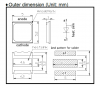
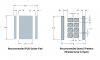
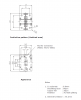
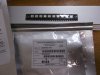
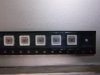
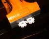
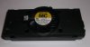
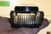
I plan on using three similar diodes made by Ushio, including the SMBB680D-1100, SMBB690D-1100, and SMBB700-1100.
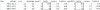
here are some stats from their spec sheet
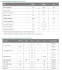
Now no information is provided regarding PAR or anything. I even asked the salesman before I realized ... why would he know that? Instead we have total radiated power and radiant intensity (RI) reported. Its too bad I can't find an RI on other brands of diodes, like LM301Bs. If someone knows, let me know.
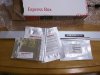
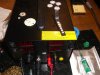
Orders done, diodes on the way.
Also list any ideas you may have for heatsinks, starboards, solder types, and related threads.
I'm not buying any premade strip as I want to craft it.
I will probably need a better soldering iron, so before I order something off Amazon, I will wait for recommendations on a kit or a workstation.
I also plan on using some higher than average nm. I see a lot of reports on action spectrum and the absorption maximas of chlorophyll a + b, which seem to vary somewhat depending if they come from reviewed scientific sources or from websites, who by coincidence or not, also sell LED lights. My only raison d'etre is that the P680 + P700 are called that because those are maxima absorption frequencies. I want to look a little more into it... let's say for photomorphogenetic reasons.
I'll need some help throughout this project. For one thing, I could use some recommendations on some deep red 660nm diodes. I will go back and read some threads (far red, etc), but 78 pages :'( along the 37 webpages + 12 pdf files + ugh...
I plan on using three similar diodes made by Ushio, including the SMBB680D-1100, SMBB690D-1100, and SMBB700-1100.
here are some stats from their spec sheet
Now no information is provided regarding PAR or anything. I even asked the salesman before I realized ... why would he know that? Instead we have total radiated power and radiant intensity (RI) reported. Its too bad I can't find an RI on other brands of diodes, like LM301Bs. If someone knows, let me know.
Orders done, diodes on the way.
Also list any ideas you may have for heatsinks, starboards, solder types, and related threads.