greg nr
Well-Known Member
So for this grow, I decided to finally add some temp and humidity control to my nursery tent. It's in my basement, and while I have a full range of environmental controls on my big tent, I didn't have anything in the nursery. So temps swang from the low 70's with lights on to the mid 60's at night, and humidity was all over the map depending on when I last watered anwhether the lights were on (rh in the basement right now is about 30% +/-).
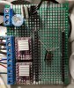
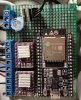
So I added a wemo mini using esp32 with a temp humidy sensor and added that to home assistant. I then used node-red to control the temp and humidity and it's doing a pretty good job so far.
Just dumb automation tricks. I guess I was bored.


So I added a wemo mini using esp32 with a temp humidy sensor and added that to home assistant. I then used node-red to control the temp and humidity and it's doing a pretty good job so far.
Just dumb automation tricks. I guess I was bored.