Stealth LED Array light .

stardustsailor

Well-Known Member
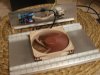
Back to the heatsink ...
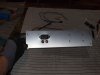
Drilling time ...

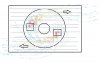
But before that some "careful" drawing ..

Remember one the 'gold rules ' of an efficient HSF cooling system ?

"The coldest part of air ,to the hottest part of heatsink "
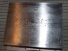
PA021605.JPG

Or vice versa ..
The hottest part of heatsink 's fins ,underneath the coolest part of fan blown air stream ....

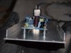
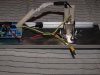
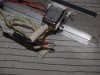
Wiring ,this time ,will be done through the heatsink ...
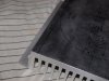
PA021607.JPG

Cheers .
 

stardustsailor

Well-Known Member
Now ,Let's go to the rear panel ....

The rear panel and it's components (wiring is missing ) .
PA021609.JPG


The pins protruding from the 'through-hole' parts ,have been trim- cut ..
( MeanWell PS-05-12 CV fan power supply )
PA021610.JPG


And then board is sprayed with Teslanol T7 ,an water-resistant ,isolating lacquer .
Film of thickness 25 microns ,isolates up to 22 kV .
PA021612.JPG


This part (circular contact ) will be cleaned again ( with IPA or Acetone or Paint Thinner ).
This contact has to be grounded.
PA021611.JPG


..An idea of the placement ....
PA021613.JPG


Cheers.
 

bicit

Well-Known Member
I'll have to keep this in mind. I'm not sure how to word this exactly, but how much water resistance does a coat like that offer? Just corrosion protection? Or will it actually protect against water droplets?

I guess I could google it... but wheres the fun in that.

ETA: I love your build threads btw. Always manages to plant a few idea seeds.
 

stardustsailor

Well-Known Member
I'll have to keep this in mind. I'm not sure how to word this exactly, but how much water resistance does a coat like that offer? Just corrosion protection? Or will it actually protect against water droplets?

I guess I could google it... but wheres the fun in that.

ETA: I love your build threads btw. Always manages to plant a few idea seeds.
Look ..
It does not pass as an IP xx grade water proofing ....

It can protect from either moist or even droplets ...
(tested)
..

Still it's nothing like a 'full epoxy boxed' circuit board ..
Good thing is that allows for service/repairs to the board ...

In the case of a full epoxy enclosed board ,once a capacitor 'swallens' ,( ~1 to $5 to replace ) ,
you throw away the whole driver/psu ( several $$ ) ....
 

stardustsailor

Well-Known Member
I occurred to me that the heat from each COB will be additive between the two locations and would require more distance between them.

Like this:


Cheers,
Mo

Mo ,you just moved the heat sources ,away from coolest point of the heatsink-fan system ...
They can be so close together ,say touching each other ..So close ..
Like if they were one single heat source ...
That close ...
As long as they are placed on the coolest point of the HSF ...

In fact you 've just decreased system's cooling efficiency by approx 30% ....


A good idea is not to place the cxa in the same 'axis ' ..
Air stream enter the heatsink fins in a complex 'twirling' motion ,rather just straight downwards ..
The cxas could be placed -respectively to the twirling motion's direction ,given by the rotor - "off axis" .
That way , maybe an increase of x% in convection ,might be possible ...

eamn.jpg
 
Last edited:

stardustsailor

Well-Known Member
Although ,ideal placement would be ,on on the top right part of wing area and the other on the bottom left .
There the stream enters the fins 'parallel' thus resistance is low ...

Where I've placed currently the two cxas ,the air stream enters the fin area ,'meeting ' the fins perpendicularly ,
like when hitting a wall ...That creates turbulance there ,and thus resistance and thus reduced convection ....

At this example of HSF ,the highest convecting fin areas ,are the one on top right and the one on bottom left ,
if the twirling motion of the downward stream has an anti- clock-wise direction ..
(at pic we see an 'X-ray' graph ,facing the base of the heatsink )


So ,underneath those areas is the highest convecting point to place the led arrays ...


Cheers.
 
Top