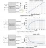
There are two main types of pots :
Linear and
Logarithmic.
http://www.beavisaudio.com/techpages/Pots/
http://sound.westhost.com/pots.htm
Linear type pots are the ones of interest .
Dimming with them , is smooth and ,of course,
LINEAR.
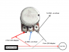
Low cost Pots usually have an action of a (almost) single turn
( 0 to max resistance value )
and can dissipate about
1/4 of W ,
meaning 250mW .
( A single low -cost pot can control up to ...~ 50 drivers ,
before it's resistive material heats up and fries ...)
View attachment 3211254
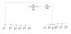
As we said ,shorting Dim- and Dim+ ,ain't such a great idea....
So a "Low Limiter' resistance must be set in series with the Pot .
In case of a single driver ,that Low Limiter should be 10K (Io= 10% of Io_max ) .
So If wiper goes to A ( 0 Ω ) , minimum resistance will be 10K .
*Low limiter can be placed in series after wiper ,also.
**If A and Wiper are used then action should be ,leds go brighter when pot's knob is
turned clock-wise ,and dim down with anti-clockwise motion.
If B and wiper are used then turning Pot's knob clockwise will dim the leds down ,
whilethe anti-clockwise rotation will increase driving Io up to max.
In case of multiple drivers :
Number of drivers ____Pot value___Dis.Power.______LowLimiter Value10%____
2 50KΩ 10mW 5K
3 47KΩ 15mW 3.6 K
4 25ΚΩ 20mW 2.5K
5 20KΩ 25mW 2K
6 20KΩ 30mW 1.6K