Still looking for a forum with the editing options I need, but I am getting there...
Meanwhile, a preliminary shopping list and some schematics.
My build:
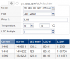
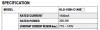
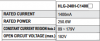
Here you can see more or less all parts on top of each other. Not all is set in stone yet. I am not sure on the supplemental LEDs, or whether I include some UVB T5s. I will be using CLU058 117W COBs (I wasn't able to find a driver that could run more than one of the 182W Class, which need 103V). I am still looking for something that can run more than two COBs but meanwhile, I will aim for the HLG-320H-C3500 driver, it has a maximum open circuit voltage of 95V, and the COBs will be run at 52V, which works fine with the holders too, that can run a max of 110V. The COBs run with a forward amperage of 1,620mA and can take a maximum of 4140mA; the driver has 3,500ma available.
Not sure if the math works out, watched most of
@Growmau5 videos and tried to figure it out from there.
@robincnn also had a couple of helpful pointers and will probably be the source of several of the things I will be using for this build.
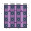
On the bottom, are the grow channels:
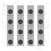
These are 300mm PVC tubes with 200mm diameter. The green dots are temperature/humidity sensors (one measuring inside, the other outside of the chamber), the yellow dots are par sensors (not sure if i will do this, but it's a nice addition to the data), the blue dots are 360° internal sprays, the light blue are 180° (the chambers are fed with fog, but the sprayers are for additional feeding, flushing and automated cleaning). The pot holes are a bit displaced to give the plants an equal and maximum amount of root space - there are grills inside the chambers separating them physically, while allowing air and water flow, to prevent as much overgrow as possible.
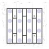
This is the Frame, which I will be making from aluminum extrusions; the heatsinks are also positioned here:
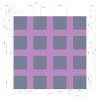
Last but not least a rough cut of cover plates. I will try to redesign some of
@Growmau5 CAD files to make it fit the CUL58 COBs and the 120mm heat sink etc:
Questions, feedback, thought, tips and ideas are welcome as always.