DIY-HP-LED
Well-Known Member
A POSSIBLE FUTURE DESIGN AND TEST BED
Yesterday I had an idea for testing the strength of silicone seals that evolved into an artsy kind of idea for an attractive water cooled fixture that could be hung over an aquarium or a light hungry living room plant.
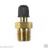
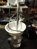
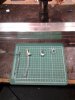
The lamp would be constructed out of a sheet of 1/4" sheet of aluminum, with either aluminum, plastic or plexiglass spacers around the outside edges to create an sandwhich of 1/4" aluminum plate, the spacing material and a 1/2" thick sheet of clear plexiglass. There would be between a 1/4" and 1/2" gap between the aluminum and plexiglass sheets that would be the water cooling chamber, baffles could be included here in a functional and attractive pattern to direct the flow of coolant. The whole thing would be glued together with clear silicone adhesive, have four eyebolts in the corners for suspension (tapped into the aluminum plate) and brass water fittings coming in through the top plexiglass sheet and clear hoses. Once assembled and covered in masking tape to prevent scratches, corners could be rounded, the edges of the assembly might be filed and belt sanded smooth and perhaps polished. Maybe some low power blue LEDs in the water chamber for effect and some food dye in the water.
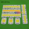
Attach the COBs to the aluminum plate with CPU tape etc, hide the drivers wires and hoses creatively, get innovative with the reflector and I could have something nice. Anyway, a good possible basement project for this winter when the grow conversion is complete.
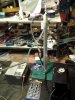
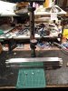
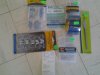
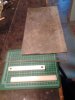
Here is a picture of some of the materials I might be working with this winter. The lamp would be the size of the sheet of aluminum and, if I wanted, have hundreds of watts of power on it, though it's only purpose then would be to grow bud. Hey ya never know, medical growing is legal where I am and recreational will probably be in the spring, so a living room christmas tree might not be out of the question!
Yesterday I had an idea for testing the strength of silicone seals that evolved into an artsy kind of idea for an attractive water cooled fixture that could be hung over an aquarium or a light hungry living room plant.
The lamp would be constructed out of a sheet of 1/4" sheet of aluminum, with either aluminum, plastic or plexiglass spacers around the outside edges to create an sandwhich of 1/4" aluminum plate, the spacing material and a 1/2" thick sheet of clear plexiglass. There would be between a 1/4" and 1/2" gap between the aluminum and plexiglass sheets that would be the water cooling chamber, baffles could be included here in a functional and attractive pattern to direct the flow of coolant. The whole thing would be glued together with clear silicone adhesive, have four eyebolts in the corners for suspension (tapped into the aluminum plate) and brass water fittings coming in through the top plexiglass sheet and clear hoses. Once assembled and covered in masking tape to prevent scratches, corners could be rounded, the edges of the assembly might be filed and belt sanded smooth and perhaps polished. Maybe some low power blue LEDs in the water chamber for effect and some food dye in the water.
Attach the COBs to the aluminum plate with CPU tape etc, hide the drivers wires and hoses creatively, get innovative with the reflector and I could have something nice. Anyway, a good possible basement project for this winter when the grow conversion is complete.
Here is a picture of some of the materials I might be working with this winter. The lamp would be the size of the sheet of aluminum and, if I wanted, have hundreds of watts of power on it, though it's only purpose then would be to grow bud. Hey ya never know, medical growing is legal where I am and recreational will probably be in the spring, so a living room christmas tree might not be out of the question!
Last edited: