Economical multi LED Chip Projects for Growing

DIY-HP-LED

Well-Known Member
Grow room air to water cooling conversion project
Harvest is hanging in the grow and the lights are off, turned the carbon filter up and opened the valve on the rad to warm it up a bit. The girls finished a week early because of growing conditions and high light levels, and the modular tube light I was gonna put in a frame over them a bit late. So a shift in priorities and a change in plan is in order, a bit of flexibility at this point I should think. Tomorrow the shop gets cleaned up and reorganized along with the rest of the disorganized disaster I call a basement, I figure the day is shot just getting me to the start line!

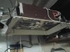
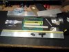
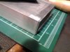
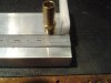
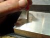
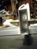
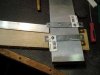
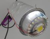
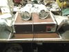
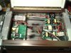
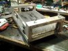
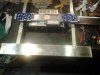
Then perhaps I can throw a couple of tubes on the bench and get to work drilling 1/2" holes, tapping fittings, plugging ends and hydrostatically testing them to 1 ATM. I'm going to prepare and test four tubes, two 24" x 3" 1" and two 60" x 3" x1" rectangular light bar tubes for 2 different water cooled light rigs. The 24" tubes will be for converting an existing 500 watt air cooled monster to water cooling and the longer 60" tubes will combined with the six 1" x 18" modules, covered earlier, into a large 60" x 24" water cooled light rig designed to cover my grow table. The new rig is composed of new and recycled drivers and LEDs, the 100 watt air cooled fixtures that are no longer needed will be stripped of useable items.

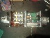
After the basement is cleaned, the shop reorganized and the bud dry, I'm stripping out the flower room doing some painting and other work, I might not make my side lights adjustable for height this grow, but should get it done next. I've got two air cooled light bars with 10 watt LEDs mounted on the walls for side/top lighting. I don't think I'll convert them to water, because they work ok now and I'm gonna need some heat in the room and since the short one runs at 100 watts and the longer one at 150 watts, they should help to keep the grow warm enough. Maybe I'll take some pictures of them and give enough of a description, that someone else who likes the idea could build their own.

Wait a minute, I'm suppose to be retired, you know, that state of existence between work and death. Well I ain't dead yet, and I plan on building more lights, growing more bud and getting as much of that free retirement money as I can! But I guess ya work until ya die anyway, I know that when ya stop learning ya might as well be dead.
 
Last edited:

Airwalker16

Well-Known Member
Something I just ran across on YouTube 1 kW water cooled LED build - Part 1 Looks like it's in progress, a real quality piece of work, not too many people could do this kinda thing. I think he over killed on the sealing, doesn't look like his system is pressurized. Beautiful project from a talented guy and one Helluva build and light.
Wow that's some bad ass shit. His box should been made out of thin aluminum though. Not wood.... but just ONE of those lights would absolutely DESTROY 4X8 Space with a good 8' ceiling heighth.
 

DIY-HP-LED

Well-Known Member
My mcpcb below led can reach 400w/mk, is the best way of heat conduction, expect to be ur best partner. If intresting, conect me:[email protected]
Thank you for your interest, I'm not sure what "mcpcb" means and I suspect English is not your first language. If you have a product that you would like to show, post a link to it here. The thermal transfer rate you mentioned of 400w/mk is impressive, not sure what it's for.

Anybody else watching know what mcpcb means? Or what he might be trying to say?
 

DIY-HP-LED

Well-Known Member
It would seem the post I responded to has been removed, as spam I suspect. Fair call, I imagine spamming is an issue.
 

DIY-HP-LED

Well-Known Member
Grow room air to water cooling conversion project
I finally got a start on converting the grow room lights to water cooling, starting with a recently completed air cooled rig I built a couple of months ago. I recently got a kill-o-watt and found it draws 460 watts from the plug, there's enough slack in the 100 watt 12 volt supply to put on another 30 watts of 660nm reds in 3 watt stars to make it close enough to 500 watts when converted.
Here's what it looks like now, before it's torn apart, we'll get into it's deconstruction later.
20160923_185759.jpg

Here are some of the materials I'll be using for the water cooling system on the new light. 2 x 24"x 3"x 1" aluminum tubes: plastic for plugs, fittings, silicone, carborundum emery cloth, aluminum plate for end caps, marine grade silicone, hydrostatic test rig, file, 1/2" drill bit, 1/2" spade bit (if you only have a 3/8" chuck on your drill) and double sided CPU tape for mounting LEDs.
20160923_162819.jpg

The ends of the tubes were filed flat, beveled inside and out and sanded with coarse emery cloth inside and out to increase silicone adhesion.
20160923_164520.jpg

Here is how the fitting and plug are in relation to each other, an aluminum end plate will be held in place with silicone over the plug. Note how I roughed up the 1/2" thick plug with a wire brush on a drill to increase adhesion. I place the fitting in the center an inch from the end.
20160923_192040.jpg

Center punching the tube before drilling a 1/8" pilot hole, then the 1/2 hole for the fitting.
20160923_192810.jpg

The fitting is a nice snug fit, I'm only going this deep, before removing. I want the fitting end near the top of the tube to make removing (bleeding) air from the tube during testing and in operation easy, not required, but a nice touch.. I'll scour the tubes with steel wool pads and rinse them off, then clean the fittings, fitting holes, tube ends and plastic plug with alcohol and a paper towel.
I also made parallel lateral gouges inside the tube ends with a screw driver to increase silicone adhesion
20160923_194015.jpg
 
Last edited:

DIY-HP-LED

Well-Known Member
Here are some options I'm exploring for attaching the tubes to a frame with the suspension system and the driver electrical box.
On the bottom of the tube I'm going to use 4" steel mending plates from a hardware or building supply store, the outside holes will be nearly perfect for 1-1/2" bolts. On the top side I can use either wooden strapping or aluminum angle or channel to sandwich the tubing. Nuts and bolt ends will face downward to make legs for setting the lamp on the floor, with a 1/4" to 1/2" clearance for the LEDs, I might use some 1" lengths of small vinyl hose on the bolt shafts to keep them tight against the aluminum, if required. I think I'm gonna go with the 1" aluminum angle, when I put it together a dab of silicone between the top of the tube and the aluminum cross piece will keep the assembly square and hopefully not wobble, or I'll need a couple of diagonal braces in diagonal corners. I think I might also use the 20" x 2" x 1' test light tube as a center tube and get creative about mounting the 5000K streetlight arrays to it. I'm not using the test rig so I might as well salvage the tube for this build. I just need to replace the 3/8 hose barb fillings with 1/2", to hook it into the rest of the lamp's cooling system.
20160923_185627.jpg
 

DIY-HP-LED

Well-Known Member
With water cooling it should be possible to have a sealed grow room or dramatically reduce the air flow through the room. The high power densities possible with water cooling make it easy to max out on light levels, especially in small spaces. This opens up the possibility of CO2 enrichment of the grow and the benefits it provides. Most small growers aren't going to buy an expensive rig to monitor and supplement CO2 or want to buy or rent gas bottles. Burning a couple of ounces of methyl alcohol in a small lamp will provide double or more the CO2 than is in ambient air (300 ppm). A cheap ebay CO2 monitor can fine tune things and help with the adjustment of the burning rate until you get close enough to the levels you want.

Here is some
text from another website

"
We will discuss these five methods briefly in turn. In order to make an effective comparison of CO2 generation, benefits and drawbacks, a std. 8' X 8' X 8' or 512 cu. ft. growing area will be used.

1. BURNING HYDROCARBON FUELS:

This has been the most common method of CO2 enrichment for many years. A number of commercial growers and greenhouses use it in their larger structures. The most common fuels are propane, butane, alcohol and natural gas. Any of these fuels that burn with a blue, white or colorless flame will produce carbon dioxide, which is beneficial. If a red, orange or yellow flame is present, carbon monoxide is being generated due to incomplete combustion. Carbon monoxide is deadly to both plants and people in any but the smallest quantities. Fuels containing sulfur or sulfur compounds should not be used, as they produce by-products which are harmful.

Most commercial CO2 generators that burn these fuels are too large for small greenhouse or indoor grow room applications. Some small ones are avai fable or a Coleman lantern, bunsen burner or small gas stove can be used. All of these CO2 generators produce heat as a by-product of CO2 generation, which is rarely needed in a controlled environment grow room but may prove beneficial in winter growing and cool area greenhouses.

The rate of CO2 production is controlled by the rate at which fuel is being burned. In a gas burning CO2 generator using propane, butane or natural gas, one pound of fuel produces approximately 3 pounds of carbon dioxide gas and about 1.5 pounds of water vapor. Approximately 22,000 BTUs of heat is also added. These figures can vary if other fuels are used.

To relate this to our standard example in an 8' X 8' X 8' growing area, if you used ethyl or methyl alcohol in a gas lamp or burner at the rate of 1.3 oz. per day, we would enhance the atmospheric concentration of CO2 to 1300 PPM if the room was completely sealed.

An enrichment standard of 1300 PPM was chosen as it is assumed that 1500 PPM is ideal, and that the plants will deplete the available CO2 supply by 100 PPM per hour. Remember, the normal atmosphere contains 300 PPM of CO2. A 100% air exchange (leakage) every two hours is assumed to be the average air exchange rate in most grow rooms and tight greenhouses. If many cracks and leaks are present, this exchange rate will increase significantly, but added CO2 (above 300 PPM) will also be lost. If a vent fan is in use, disregard CO enrichment, as it will be blown out as fast as it is generated.

A circulation fan is beneficial, as it moves the air about in the greenhouse or grow room. If the air is still, it can cause a "depletion layer effect". This effect causes the CO2 right next to the plant leaf to be quickly depleted. If fresh air carrying additional CO is not brought to this surface, photosynthesis and growth will diminish and eventually cease.

There are a number of factors involved in keeping the CO2 content at the desired concentration level. 1. If the greenhouse or grow room is not tightly sealed up, add up to 50% to the CO2 generator production volume. 2. If temperature is increased fiom 70 F to 90 F, add 20% to the volume generated, and vice-versa. 3. If the grow area contains large or tightly spaced plants, add 20% to 30% to the CO2 volume generated.

If more light is used, more CO2 can be utilized and should be produced proportionately up to the practical limit of 5,000 footcandles per square yard and 1500 PPM CO2 atm. content. When more CO is generated, more water and plant nutrients should be used, again to a practical limit of 2X normal. lf your plants are going to grow faster because of CO2 enrichment, they will need more nutrient and water.

The last factor to consider in maintaining a set CO2 level is the size of your growing area. This is simply done for gas burning and following methods by setting up a mathematical ratio. In our "standard" room (8' X 8' X 8'), we have 512 cubic feet. If your growing area measures 10' X 10' X 20', you have 2,000 cubic feet of volume to contend with. If you want to use the ethyl alcohol/gas-lamp enrichment method, set up the ratio using l.3 oz. by weight of alcohol per day gives:

1.3 oz./day = 512 cu. ft.
------------------ -------------------

X oz./day = 2,000 cu. ft.

Then cross multiply: 512 X = 1.3 X 2,000. Dividing both sides by 512 gives you X = (1.3 X 2000)/512, solve for X. X = 5 oz.
You need 5 oz. of ethyl alcohol per day in a 10' X 10' X 20' grow area to generate the same amount (1300 PPM) of CO2 as in a 512 cu. ft. room.

To generate 1500 PPM above the available CO2 (200 PPM) in the same size area, set up the ratio:

1300 PPM = 5 ounces

-------------- ------------

1500 PPM = X

X = (5 X 1500)/1300 = 5.77 ounces.

NOTE: One pound of CO is equivalent to approximately 8.7 cu. ft. of gas at standard temperature and pressure.

If different hydrocarbon fuels are used, the heat content, in terms of B.T.U. should be taken into account. If the BTU per hour rate is half that of ethyl alcohol, twice as much must be burned to generate the same approximate amount of CO2 desired. The amount of CO2 generated depends on the carbon content of the fuel being used. The BTU per hour heat content can be obtained from literature or suppliers."
 
Last edited:

DIY-HP-LED

Well-Known Member
Grow room air to water cooling conversion project update
I've got the two 24" tubes completed and the silicone curing. Did some work cleaning out the grow and I got the air cooled beast on the bench ready for deconstruction. I cooled it with two duct fans sucking and blowing in each end, along with a blower and 16' of ducting. It probably weighs around 40 pounds with a 12 3/4" x 20" x 1/4" aluminum plate attached to a large 10" x 18" heatsink with 1/4" bolts. Hot air heating floor registers are on each end to direct air flow, attached to a sturdy suspension frame made of aluminum channel.
20160926_194954.jpg


Here is what it looks like inside, the top cover is hinged and is magnetically sealed with magnets epoxied under the front edge, steel inserts in the lid keep it tight. Here are 3 X 100 watt drivers, 2 x 50 watt drivers, a 100 watt 12 volt supply and a buck converter. The skin and reflectors are custom bent aluminum flashing from a building supply place. All the heavier aluminum including the heatsink are from the local scrap yard.
20160926_195027.jpg

I didn't count the construction hours on this thing, but it was a lot more than I'm going to spend converting it to water cooling. Tomorrow I hope to start in on tearing it apart and working on the grow room rebuild.
 

DIY-HP-LED

Well-Known Member
Grow room air to water cooling conversion project update
The cooling tubes for the new light are curing, the grow room prepped and ready for painting, The big air cooled light has been stripped and the carcass set aside, and the test light has also been stripped down. I should be ready for hydrostatic testing and assembly of the small water cooled lamp tomorrow.

Here is a picture of the stripped carcass of the 500 watt air cooled light. I consists of a 1/4" aluminum plate, heatsink and suspension frames. I left the electrical connector and switch on it as well.
20160927_225703.jpg
 

DIY-HP-LED

Well-Known Member
Grow room air to water cooling conversion project update
Hydrostatic Testing

One of the 24"x 3" x 1" tubes failed the hydrostatic testing, at I figure 20+ psi (gauge tube) an end plug failed. On examining the plug and end I found the thickly applied silicone adhesive had not cured completely and was wet and soft in places after a 36 hour cure. I repaired the tube and I have it curing, the other tube now has a hose from an aquarium pump in one fitting blowing air through the tube and I'm gonna apply a few degrees of gentle heat (5 -10 C) to the tube to help the silicone cure faster.

I'll move on to completing the two 60" tubes and other work on the small lamp and leave the two short tubes to cure for a few days before resuming testing. I tested the 20' x 2" x 1" test lamp tube to 50 psi (estimated from gauge tube) and it passed no problem, so the idea is sound, just need to adjust the curing time. I'm thinking of picking up some two part silicone epoxy adhesive at the hardware store to try on the larger tubes, maybe I can avoid curing issues this way. I'm also considering using 1/4 aluminum plates on the larger tubes as plugs, but it's difficult to work with and would require a lot of filing. Though if I took my time, did a good job of beveling and fitting on the plugs and ends, I could use JB Weld epoxy and get a bond that is very strong.
 

DIY-HP-LED

Well-Known Member
Grow room air to water cooling conversion project update
Hydrostatic Testing part 2

I retested the failed tube after a five day cure and the repaired end held, but the un repaired end failed under one ATM with a small leak, so I upped the pressure until it failed completely with a pop at about 30+ psi. Upon examination I found that the first pressure test had weakened the silicone seal and water encroached into the uncured joint. I don't have time to wait another four or five days for silicone to cure, so I repaired the failed end with an epoxy made for aquariums that will cure much quicker. The other tube passed the 1 atm test , but leaked around one of the fittings slightly, I tested this tube up to 40 psi and the ends remained tight. Both tubes will be retested in a couple of days, the tube with the fitting leak failed because I didn't screw it in far enough and it has been repaired.

While the tubes were curing I was busy finishing up the electrical box, center tube and support frame. When the tubes are cured and tested, then I can begin final assembly by mounting the outside tubes, sticking on the COBs and wiring them up to the drivers. The electrical box is made by combining two ATX power supply boxes on two 1/2" steel angle pieces that tie into the two 1" aluminum angle cross supports.

The electrical box is crowded with four 100 watt and one 50 watt driver, a buck converter is mounted on the front of the box next to the power switch.
20161002_125909.jpg

The underside of the electrical box has a 100 watt 12 volt power supply and a 50 watt driver mounted on the bottom, on either side of the central 20" x 2" x 1" water cooling tube (from the test lamp). So far there are 2 x 25 watt street light 5000K arrays and a full spectrum grow chip in the center, 2 x four band COBs will also go on the center tube. The tube is mounted on the electrical box with silicone adhesive and two cross plates and four bolts. Here it is shown with the two aluminum cross angles attached to the steel angles and one outside cooling tube laid in place to give an idea what the finished lamp will look like.
20161002_193254.jpg

If the epoxy works out and it looks like it will, I think I'm going to use it instead of silicone on the long 60" tubes. The epoxy has a claimed shear force of over 7000 lbs with a 36 hour cure and is recommended for aquarium construction. It appears to be a better choice for this job, with a stronger bond than silicone and a much faster curing rate, but the pressure test will tell the tale. The only draw back to the epoxy is that it's not rated for more than 200 degrees F, but if it ever reaches anywhere close to that in this application, the lamp would be toast long before. Silicone adhesive can take extremely high temperatures, but that's not important for this application. Thermal shut off for the lamp will be set at 35 degrees C by a digital thermostat in series with the power supply. Fail safe shut down will provided by the 40 C thermal switch and an 65 C thermal fuse in series with the power switch.
 
Last edited:

DIY-HP-LED

Well-Known Member
Correction to above
The epoxy has a claimed shear force of over 1700 lbs with a 36 hour cure and is recommended for aquarium construction.
 

DIY-HP-LED

Well-Known Member
Grow room air to water cooling conversion project update
Hydrostatic Testing part 3

I tested the two 24" x3" x1" aluminum tubes today, and yet another silicone adhered end failed. I'm losing confidence in using silicone to plug the tube ends, it doesn't stick to the aluminum tube sufficiently. The epoxy seems to work quite well and I repaired the tube using epoxy and will test it tomorrow or the day after. One tube is tested and ready to go and I might use it tomorrow to lay out the holes in both sides of the support frame and then mount it. I might even stick on the LEDs and wire up that side. When the other tube passes hydrostatic testing it will then be applied and I can finish up the lamp and begin bench testing.

I'm glad I took the time to setup the hydrostatic testing, when the lamp is assembled I don't want to discover leaks during bench testing! Testing is a good way to determine leak resistance and the strength of the adhesive bond. In this case it revealed that silicone adhesive might not be the best choice for this application, though the 20" x 2" 1" test lamp tube and other tubes using silicone passed the pressure test, I want better, more consistent results. For the longer tubes I'm going to use epoxy and 1/4" aluminum plates as end plugs instead of plastic. The epoxy produces a much stronger bond and cures quicker. Along with the change in plugging methods, I hope the long tubes will pass the pressure testing on the first round.

The testing and subsequent failures have slowed things down (mostly waiting for curing), but the build hours haven't gone up that much. I've learned quite a bit about sealing and testing the tube ends and hopefully this will pay off on the next build of the big 60" light. In building the small light first I've learned a few other things that will end up in the design of the larger light rig.
 

DIY-HP-LED

Well-Known Member
Grow room air to water cooling conversion project update
Hydrostatic Testing part 4

I tested the remaining tube today that has epoxy on both ends and it passed the 1 ATM (and higher) test, epoxy appears to be the answer. I decided to test the tube that passed yesterday that had one remaining silicone end and it failed at about 35 psi. I had removed the thin aluminum end plate cover so that I could observe the seal under pressure and it didn't leak at 1 ATM. When I raised the pressure to over 30 psi I noticed the end bulging and a 1" bubble of cured silicone formed on one side, filled with un-bleed trapped compressed air and then water, I raised the pressure further and blew the end plug and silicone out with a pop. The end that I used epoxy on was tight and undistorted. I repaired the failed end with epoxy and it's curing now and soon another 1/8" layer of epoxy will go on top of the plug to bring it flush with the end of the tube. I'll allow this to cure overnight and retest everything tomorrow to 1 ATM. Silicone will make tubes water tight, but if you want the extra security of pressure testing, use and appropriate epoxy adhesive.

For the longer 60" tubes I'm changing the sealing method and adhesive. I'm going to use 1/4" thick 3" x 1" aluminum plates cut on a table saw with a carbide tipped blade. Using the table saw, I hope to make a 1/8" off set around the end plate edges and use JB Weld epoxy to adhere and seal it to the tube ends.
 
Last edited:
Top