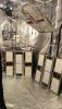
They can’t take the 240 c2100?I use a hlg-150h-54b for two 272 boards View attachment 5365867View attachment 5365868
DIY with Quantum Boards
- Thread starter robincnn
- Start date
sfw1960
Well-Known Member
All good indeed, either setup works.They can’t take the 240 c2100?
They're actually right on 54 VDC on a HLG 240-54A (a pr max'd) and if you're going to run a pair in series the CC range is covered for 108 VDC.
I'm 90+% decided to run a quad of them on a HLG 480-54B, I'm probably finally done, DONE - hacking on those frames now.
The 272 Rspec FR boards are down the middle of the ends.
They require a different voltage for them opposed to the V1 288 which says 52 VDC on the silkscreen so some kinda rEwARiN' is in order then I can flame on with it!
Ya know, testing 1,2 ... Testing 1,2,3...
KaFOOF! FLAME ON!!!!!!!!!!!
Really , it's the weight that makes me a bit nervous. I might cut a little ½ EMT and put it in the middle if it seems "more" sKEErReY than it was before, it's not quite another ten lbs guessing for wire weight too but it's Schwiingin' on cheap tubing W/ peanut butter welds lol!


Sade
Well-Known Member
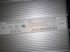
Absolutely will send a pic here shortly and thank you.Could you maybe send a pic of the label on the driver for a full model nr? Afaik theres several versions of the inventronic drivers with different voltage/current. You might have the wrong driver. Not sure but i dont think all the inventronics are programmable.
How does dimming work without the controller? Can you use a standard resistive pot?
Sade
Well-Known Member
Wired in Series-Parallel circuit from what hlg said to do but electrician at my job thinks it should just be in series. What are your thoughts?Could you maybe send a pic of the label on the driver for a full model nr? Afaik theres several versions of the inventronic drivers with different voltage/current. You might have the wrong driver. Not sure but i dont think all the inventronics are programmable.
How does dimming work without the controller? Can you use a standard resistive pot?
Attachments
-
 1.3 MB Views: 18
 -
 269.2 KB Views: 17
TheChemist77
Well-Known Member
Just found this thread, new to the quantum board and really led thing. I’ve been reading up on best diodes and fixtures and ran across boards on Amazon then looked up a 240 watt mean well driver but don’t know where to buy heat sinks to fit boards. Can any one send me a link to find the right size heatsinks? Also how hard is it to build these,wire them and so on? Also is it reAlly that much cheaper to build your own? As I noticed the drivers are pretty pricy… better yet can anyone recommend me a whole list of what to get at Amazon to build say 3,,, 2 120 watt boards s o 6 boards, 3 240 watt drivers heatsinks and anything else I may need? I hope I can build enough lights to cover a 6x6 area. Thanks for any info and help!
Rocket Soul
Well-Known Member
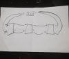
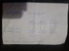
Youd need to wire 2 boards in series, 3 parallel circuits. Currently you have pictured 3 boards in series, nothing in parallel; its just 2 separate serial connections of the same boards if i understand your diagram correctly. Should not work with that driver. Your need 2 boards in series, 3 parallel circuits.Wired in Series-Parallel circuit from what hlg said to do but electrician at my job thinks it should just be in series. What are your thoughts?
sfw1960
Well-Known Member
I'll send you a PM then...Just found this thread, new to the quantum board and really led thing. I’ve been reading up on best diodes and fixtures and ran across boards on Amazon then looked up a 240 watt mean well driver but don’t know where to buy heat sinks to fit boards. Can any one send me a link to find the right size heatsinks? Also how hard is it to build these,wire them and so on? Also is it reAlly that much cheaper to build your own? As I noticed the drivers are pretty pricy… better yet can anyone recommend me a whole list of what to get at Amazon to build say 3,,, 2 120 watt boards s o 6 boards, 3 240 watt drivers heatsinks and anything else I may need? I hope I can build enough lights to cover a 6x6 area. Thanks for any info and help!
Sade
Well-Known Member
Youd need to wire 2 boards in series, 3 parallel circuits. Currently you have pictured 3 boards in series, nothing in parallel; its just 2 separate serial connections of the same boards if i understand your diagram correctly. Should not work with that driver. Your need 2 boards in series, 3 parallel circuits.
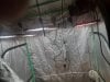
Thank you so much man ok so I have 3x triple board heatsinks from hlg. 6x boards total so each heatsink has 2 boards on each end and middle is blank. Is there any possible way you could make a wiring diagram sketch. I'd really appreciate it man and thank you again for the help. Also sent pictures of how the heatsinks are placed with boards on them. Have them where positive on the left side and - on right side facing towards back of tent and driver is at back of tent too.Youd need to wire 2 boards in series, 3 parallel circuits. Currently you have pictured 3 boards in series, nothing in parallel; its just 2 separate serial connections of the same boards if i understand your diagram correctly. Should not work with that driver. Your need 2 boards in series, 3 parallel circuits.
Edit: will that driver be enough or do I need a second one?
Attachments
-
 1.3 MB Views: 12
 -
 2 MB Views: 12
 -
 1.9 MB Views: 15
 -
 635.7 KB Views: 14
Rocket Soul
Well-Known Member
Dude you insist on uploading the one important pic upside down, lol. No worries.Thank you so much man ok so I have 3x triple board heatsinks from hlg. 6x boards total so each heatsink has 2 boards on each end and middle is blank. Is there any possible way you could make a wiring diagram sketch. I'd really appreciate it man and thank you again for the help. Also sent pictures of how the heatsinks are placed with boards on them. Have them where positive on the left side and - on right side facing towards back of tent and driver is at back of tent too.
Edit: will that driver be enough or do I need a second one?
Sorry i dont have pen and paper so wont do a wiring diagram but this is easy enough to explain.
On each heat sink connect the boards in series (minus on first board to plus on second board) Make sure youre consistent here, all first boards of the series on the same side. This is your series connection, now lets do the parallel:
On each heatsink connect the first board plus to driver plus. On the second board of each heatsink, connect second board minus to driver minus. If you like to draw it up first just do it on the schematic upside down pic and upload, ill give you feedback to make sure.
These boards contain diodes that cannot handle reverse current so if you connect them up wrong you will probably destroy the boards so make sure you get it right.
On the driver: it doesnt look like an ideal fit to me unless its one of those new constant power drivers. If its a pure constant current driver its not ideal, youd only get about 85% of the watts from the driver, assuming 57V per board. Ill see if i can have a look see in the datasheet.
Edit: checked the datasheet and you should be good, its a constant power driver. If you upload a pic of what youd connect according to instruction above ill have a look and ok it.
Sade
Well-Known Member
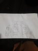
Yea that seems much better how does that look?Dude you insist on uploading the one important pic upside down, lol. No worries.
Sorry i dont have pen and paper so wont do a wiring diagram but this is easy enough to explain.
On each heat sink connect the boards in series (minus on first board to plus on second board) Make sure youre consistent here, all first boards of the series on the same side. This is your series connection, now lets do the parallel:
On each heatsink connect the first board plus to driver plus. On the second board of each heatsink, connect second board minus to driver minus. If you like to draw it up first just do it on the schematic upside down pic and upload, ill give you feedback to make sure.
These boards contain diodes that cannot handle reverse current so if you connect them up wrong you will probably destroy the boards so make sure you get it right.
On the driver: it doesnt look like an ideal fit to me unless its one of those new constant power drivers. If its a pure constant current driver its not ideal, youd only get about 85% of the watts from the driver, assuming 57V per board. Ill see if i can have a look see in the datasheet.
Edit: checked the datasheet and you should be good, its a constant power driver. If you upload a pic of what youd connect according to instruction above ill have a look and ok it.
Attachments
-
 646.5 KB Views: 16
Rocket Soul
Well-Known Member
Thats correct. And right side upYea that seems much better how does that look?
sfw1960
Well-Known Member
I figured you would exercise more patience than I after beating myself up all day lol
@Rocket Soul you are appreciated here too!!!!!!
@Rocket Soul you are appreciated here too!!!!!!
Sade
Well-Known Member
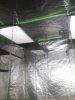
Full mother fucking power baby haha thank you so much man.Thats correct. And right side up")

Rocket Soul
Well-Known Member
Thats correct. And right side upYea that seems much better how does that look?
Try to get it locally where construction people go, online is generally expensive with shipping long stuff.Ok another question what's a great site to order anodized angled aluminum to build a frame
GreenNotYellow
Member
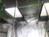
Imagine running water through those pipes to adjust temperature!Full mother fucking power baby haha thank you so much man.View attachment 5366423
sfw1960
Well-Known Member
Old tech chugging along with the HLG QB132's - planning to wrap up door #1 tomorrow - I cut down 2 frames and pulled the drivers and aluminum mounts to hang outside - four screws and a couple wire drops through the roof hatch and Shazam, more headspace!
(I don't think I can fit another row of four but I'ma measure tomorrow, but the 2 DZ does work)
Not straight to the moon, Alice but almost against the poles!


(I don't think I can fit another row of four but I'ma measure tomorrow, but the 2 DZ does work)
Not straight to the moon, Alice but almost against the poles!