DIY: SSL complete protection for two LED drivers
- Thread starter stardustsailor
- Start date
CanadianONE
Well-Known Member
Just for informative purposes ,except the easy way of perforated board ,
a blank PCB can be used and with the method of " laser printer toner transfer "
( plenty vids on YOUTUBE ,about this technique ) ,a more " clean" result can be obtained .
Still it needs etching and drilling the holes onto it ...
And for sure ,the whole procedure it's somewhat tricky and time consuming ,for the begginer at least.
But the result obtained is far better than a perforated board .
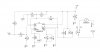
The pic below depicts the circuit described at this thread ,for 4x LED drivers ,
made with the "laser printer toner transfer method" .
The board has not been etched yet.
After etching in a chemical solution ( warm water & Sodium Persulfate ) ,
all the copper that is not covered with the toner ,is going to be disolved in the etching solution .
Afterwards the toner is removed with acetone and then the PCB holes have to be drilled.
Then the various parts will be soldered on the board.
Cleaning the flux residues with Isopropyl alcohol follows
and lastly the copper side is painted ,to protect the copper from corrosion .
View attachment 3469804
I know that this might be way over most of you ,but still you never know ,until you try ...
Some might try it out ...
Just do not forget that myself-for example- ,couple of years ago did not know shit about electronics ...
Neither i'm someone special or different than most are ,
neither I've became an expert in electronics already ...
But for sure I can make various " bits 'n' pieces ",
regarding LED grow lights and not only about them ...
All one has to do is to take the first step ...
A journey of a thousand miles begins like that ...
With a single step.
....And maybe with a big fat joint along ,for the way...
Cheers.

Have you completed this beautiful piece of art yet? I would love to see some photos of the finished product when done if it isn't already. Cheers
CanadianONE
Well-Known Member
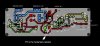
Would you happen to have the gerber files for this layout? Also can I connect three separate fans to this circuit? I am running a Meanwell HLG-120H-C1400A to power three CXB3070 AB 3000K COBS on Rosewill RCX-Z1 CPU coolers and this is what I would like this circuit for.Fan fail protection for a single driver :
Just use the "first-half " of the whole circuit ...
Like that ...
View attachment 3472157
Cheers.
Abiqua
Well-Known Member
^ Good question @CanadianONE about the fans...
So, @stardustsailor
If you are able to answer these questions, we would be humbled, thank you! I know you are busy as shit and appreciate anything you have to offer.
#1 multiple fans: Especially fans wired in series? I almost thinking that due to the Tach, 1 circuit for each fan as well?
#2 Would there be an entirely separate procedure if using a 5v DC supply for fans?
#3 Is a replaceable Rated fuse an acceptable replacement for a Resettable Fuse? Is ease of use the advantage here?
#4 Is there still a place for a Thermostatic Fan Switch, essentially mounted on NON-fan components, but still routed into your circuit?
#5....I started an Online Order for components...Also building just a single driver board.....As for the range you have given to a couple of components:
C3,C4 and C7, I picked the absolute highest rating you suggested, as I didn't know if price was a factor here, maybe you can clarify?
stardustsailor
Well-Known Member
Yes ,just look at the pics ,towards the end of the previous thread's page ....Have you completed this beautiful piece of art yet? I would love to see some photos of the finished product when done if it isn't already. Cheers
Gerber no ,I'm afraid ...Just DipTrace files ...(and then you can convert to gerber files ...I think ... )Would you happen to have the gerber files for this layout? Also can I connect three separate fans to this circuit? I am running a Meanwell HLG-120H-C1400A to power three CXB3070 AB 3000K COBS on Rosewill RCX-Z1 CPU coolers and this is what I would like this circuit for.
-Three separate fans = three separate circuits ,with their AC outputs connected in series ..
If one of three fans fails ,the single driver switches off ...
#1 Yes ,each tach wire of fan to it's fan fail circuit .multiple fans =multiple circuits .^ Good question @CanadianONE about the fans...
So, @stardustsailor
If you are able to answer these questions, we would be humbled, thank you! I know you are busy as shit and appreciate anything you have to offer.
#1 multiple fans: Especially fans wired in series? I almost thinking that due to the Tach, 1 circuit for each fan as well?
#2 Would there be an entirely separate procedure if using a 5v DC supply for fans?
#3 Is a replaceable Rated fuse an acceptable replacement for a Resettable Fuse? Is ease of use the advantage here?
#4 Is there still a place for a Thermostatic Fan Switch, essentially mounted on NON-fan components, but still routed into your circuit?
#5....I started an Online Order for components...Also building just a single driver board.....As for the range you have given to a couple of components:
C3,C4 and C7, I picked the absolute highest rating you suggested, as I didn't know if price was a factor here, maybe you can clarify?
#2 Nope.The circuit will operate from a 5 VDC PSU also ...( up to 28 VDC ).
-Thing is that you will have to change the relay(s) .
Instead of 12 VDC rated coil ,you 'll have to use 5VDC rated coil ones .
-Also the LM2907N-8 has to be used ,as the the LM2917N-8 has a buit-in zener,
connected at it's Vcc pin ,meaning it has to have a min Vcc of ~8 VDC .
#3 Of course .A fuse is always a fuse and does what a fuse should do .No matter is it resettable or replaceable ..
#4 For what reason ? Routed to switch off the relay ? ( meaning to switch off the drivers ? )
#5 C3 is a "smoothing cap " ,as it smoothes from power transients .
You can have it there ,but you can skip placing that cap,also .
If placed, it should be an electrolytic cap of 47 uF min . value , up to 470 uF max value ( 16-25-35 or 50 V ).
C4 is the "signal coupling " cap .That one should be 1 uF ,with it's positive side ,towards the Tach wire input .
** The transistor shown at figure b ) ,is already inside the fan's circuitry .
It has it's collector "floating" (not connected) ,thus the 4K7 ( R1 of the circuit ) resistor ,
" pulling it up " to +12VDC ...Tach signals of course ,are of 0 VDC .(And not "below ground" ,like i.e. - 12VDC )
C7 is a " filter cap" for the LM29x7 's "charge pump " .This one also should be of 1 uF .
Positive side towards pin #3 of the LM29x7 .
Cheers.
Last edited:
stardustsailor
Well-Known Member
Here you can read more info
http://www.ti.com/lit/an/snaa088/snaa088.pdf
Check pages : 4 -5 -8 & 9 ..
The LM2907N-8 used in the circuit presented at this thread is "wired " as a "simple speed switch "
** with the selected values of 200 K resistor and 2x 100nF timing caps -
connected in parallel- :
At our circuit above, " Load " (relay,thus LED driver ) is energised when :
F >= 1 / (2* 200'000 ohms * 0,0000002 Farads ) = 1 / 0,08
Meaning that the relay will be switched ON ,
when the input frequency at pin #1 of the LM2907 ,is equal or higher of 12.5 Hz .
Each fan rotor full 360° rotation ,produces 2 tach signals .
1 ) 12,5 tach signals per sec / 2 tach signals per round = 6,25 rounds per second .
2 ) 6,25 rounds per second * 60 secs per min = 375 rounds per minute.
The fan has to rotate ,at least ,with 375 rpm
,in order for the relay to switch ON the LED driver .
If fan speed drops below 375 rpm ,LED driver is switched OFF.
Last edited:
stardustsailor
Well-Known Member
One thing to note :
There's a 510K resistor in the fan fail circuit .
( one end is connected between the two 5K1 resistors ,which form a 50%-50% voltage divider and the other end of the
510K resistor is connected to the collector (pin #5 of LM2907N-8 ) of the "floating NPN transistor " inside the LM2907N-8 .
That resistor adds " hysteresis" ..
I've noticed that when setting the threshold for higher RPM of the fan ,the relay was chattering ..
I.e when I've used lower capacitor and or resistor values ( 100K instead of 200K and/or 100 nF instead of 200nF ).
Depending on the fan's ability to reach the set threshold and of course the coil resistance and the coil energizing voltage of the relay used ,chattering may occur or may not ...
It seems that the Phanteks PH-F140XP takes some time to reach a set RPM threshlod of say 700-800 rpm and the relay used ,was chattering enough before it got fully energized.
That is an unwanted situation ,as the LED drivers should not be switched ON & OFF rapidly ,because
their inrush current suppression ( a NTC thermistor ) does not have the time to "cool down ".
Meanwell suggests that the LED drivers should not be switched ON & OFF rapidly (like when "relay chattering " occurs),
as the LED drivers maybe damaged (and the relay contacts will arc , and eventually will be "welded" with each other .)
In order to prevent chattering it is wise to set a low RPM limit / threshold and / or have a hysteresis resistor .
That resistor pre-energizes the relay coil ,by allowing a small amount of current to flow through the relays' coil to ground (via one of the two 5K1 resistors)
Still it's value has to be large enough ,so that the relay is not fully energized.
I've picked a value of 510K as an "all-around" value for most of the 12 VDC relays .
Lowering the value of that resistor ,increases hysteresis (thus decreasing the possibilities for relay chattering ).
You can experiment ,for choosing the value of that resistor.
(depending of fan & relay used ).
In case you 've set a higher RPM limit threshold
(like when using 100K timing resistor and 100nF timing cap = 1500 rpm threshold )
If then you experience any relay chattering ,then decrease the value of that "hysteresis " resistor step by step *, until no relay chattering occurs.
*step by step : 510K > 470K > 430K >390K > 360K > 330K > 300K > 270K ...and so on ...
Last edited:
CanadianONE
Well-Known Member
Would it be possible to get the diptrace files for the single driver fan protection circuit?Yes ,just look at the pics ,towards the end of the previous thread's page ....
Gerber no ,I'm afraid ...Just DipTrace files ...(and then you can convert to gerber files ...I think ... )
-Three separate fans = three separate circuits ,with their AC outputs connected in series ..
If one of three fans fails ,the single driver switches off ...
#1 Yes ,each tach wire of fan to it's fan fail circuit .multiple fans =multiple circuits .
#2 Nope.The circuit will operate from a 5 VDC PSU also ...( up to 28 VDC ).
-Thing is that you will have to change the relay(s) .
Instead of 12 VDC rated coil ,you 'll have to use 5VDC rated coil ones .
-Also the LM2907N-8 has to be used ,as the the LM2917N-8 has a buit-in zener,
connected at it's Vcc pin ,meaning it has to have a min Vcc of ~8 VDC .
#3 Of course .A fuse is always a fuse and does what a fuse should do .No matter is it resettable or replaceable ..
#4 For what reason ? Routed to switch off the relay ? ( meaning to switch off the drivers ? )
#5 C3 is a "smoothing cap " ,as it smoothes from power transients .
You can have it there ,but you can skip placing that cap,also .
If placed, it should be an electrolytic cap of 47 uF min . value , up to 470 uF max value ( 16-25-35 or 50 V ).
C4 is the "signal coupling " cap .That one should be 1 uF ,with it's positive side ,towards the Tach wire input .
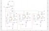
View attachment 3474643
** The transistor shown at figure b ) ,is already inside the fan's circuitry .
It has it's collector "floating" (not connected) ,thus the 4K7 ( R1 of the circuit ) resistor ,
" pulling it up " to +12VDC ...Tach signals of course ,are of 0 VDC .(And not "below ground" ,like i.e. - 12VDC )
View attachment 3474647
C7 is a " filter cap" for the LM29x7 's "charge pump " .This one also should be of 1 uF .
Positive side towards pin #3 of the LM29x7 .
Cheers.
stardustsailor
Well-Known Member
Later when I 'll get back home ....Would it be possible to get the diptrace files for the single driver fan protection circuit?
I'm out for havin' some fun ,right now...
CanadianONE
Well-Known Member
No rush just figured I would ask and when you have a chance you could pop it online. Appreciate it very much. One quick question as you stated I need three circuits for three fans, Could I possibly combine the three circuits into one? If not I will just create three isolated circuits but on one PCB.Later when I 'll get back home ....
I'm out for havin' some fun ,right now...
stardustsailor
Well-Known Member
You mean 3x fans and only one driver in the system ?No rush just figured I would ask and when you have a chance you could pop it online. Appreciate it very much. One quick question as you stated I need three circuits for three fans, Could I possibly combine the three circuits into one? If not I will just create three isolated circuits but on one PCB.
Aka 3 fans fail protection for a single driver ?
(Any of the fans fail ,driver switches OFF )
If so yes ...
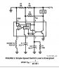
It can be done ...You will need a single relay ,but still 3x LM2907N-8 ICs and their external components ...
you will have to connect their "floating transistor " outputs in series ...
LM2907 #1 collector (pin#5) to relay coil and pin#4 ( emitter )
to LM 2907#2 collector (pin#5 ).
LM2907#2 emitter pin ( pin #4),to LM2907#3 collector and finally
emitter of LM2907#3 (pin #4 ) to ground ...
That way ,If any of the LM2907 switches off its transistor(output ) ,the relay also swithes OFF .
CanadianONE
Well-Known Member
Wonderful thank you, It might take some time to digest all the information as I am fairly new to the electronics scene also. But in the end I believe this will be the best option at keeping things compact and nice looking lolYou mean 3x fans and only one driver in the system ?
Aka 3 fans fail protection for a single driver ?
(Any of the fans fail ,driver switches OFF )
If so yes ...
It can be done ...You will need a single relay ,but still 3x LM2907N-8 ICs and their external components ...
you will have to connect their "floating transistor " outputs in series ...
LM2907 #1 collector (pin#5) to relay coil and pin#4 ( emitter )
to LM 2907#2 collector (pin#5 ).
LM2907#2 emitter pin ( pin #4),to LM2907#3 collector and finally
emitter of LM2907#3 (pin #4 ) to ground ...
That way ,If any of the LM2907 switches off its transistor(output ) ,the relay also swithes OFF .
stardustsailor
Well-Known Member
Oh! Do not think for a moment that myself ,I'm better than you in electronics.Wonderful thank you, It might take some time to digest all the information as I am fairly new to the electronics scene also. But in the end I believe this will be the best option at keeping things compact and nice looking lol
I know only some basic stuff ,which are quite easy to learn with a bit of web-studying ...
Thank Guod ,that I had a great inspirator !
I hope that he chimes into all these ...
You see ,is not uncommon for me ,making ridiculous mistakes ...
And Guod used to be always there ,to put me back in "line" ...
Those were great moments...
I was always thirsty and keen to learn from him ...
Now ,lately ,I miss all those great moments ...
Although I'm southern european and him being a northern one ..
There are more things that "unite" us ,than separating us ..
I will always have the greatest respect for him.
He changed my life .
Literally speakin' ...
I wish I could the same with others.
Anyway ...
Electronics is as addictive as growing ...
Maybe even more ...
Cheers.
stardustsailor
Well-Known Member
Another interesting option of "fan fail" protection Intergrated Circuit chip is this :
http://datasheets.maximintegrated.com/en/ds/MAX6684.pdf
Although ,comin' only in a SO-8 package (tiny chip ) ,will make the soldering a bit of PITA ....
Still ,is an interesting option ,as it works with 2-wire fans .
http://datasheets.maximintegrated.com/en/ds/MAX6684.pdf
Although ,comin' only in a SO-8 package (tiny chip ) ,will make the soldering a bit of PITA ....
Still ,is an interesting option ,as it works with 2-wire fans .
salmonetin
Well-Known Member
...maybe with soic to dip adaptator....

Saludos
Saludos
stardustsailor
Well-Known Member
Yes,quite good solution......maybe with soic to dip adaptator....
Saludos
As long as you'll find the IC already soldered to the adaptor ..
Thanx ,Salm
salmonetin
Well-Known Member
...the ic already soldered not... but reflow solder its a big help...you can solder in groups... are small pieces...
...i know its more labor too.... ...i saw more info... pcb ...stencil...

https://www.sparkfun.com/products/494
http://www.proto-advantage.com/store/product_info.php?products_id=400008

http://www.proto-advantage.com/store/product_info.php?products_id=2220001
pd..other wago conectors...
http://www.wago.com/infomaterial/pdf/51230818.pdf
http://www.farnell.com/datasheets/483287.pdf
Saludos
...i know its more labor too.... ...i saw more info... pcb ...stencil...
https://www.sparkfun.com/products/494
http://www.proto-advantage.com/store/product_info.php?products_id=400008
http://www.proto-advantage.com/store/product_info.php?products_id=2220001
pd..other wago conectors...
http://www.wago.com/infomaterial/pdf/51230818.pdf
http://www.farnell.com/datasheets/483287.pdf
Saludos
Last edited:
CanadianONE
Well-Known Member
Funny I was looking at the datasheet for this IC earlier today lol Just not great at coming up with a circuit to work with something yet lolAnother interesting option of "fan fail" protection Intergrated Circuit chip is this :
http://datasheets.maximintegrated.com/en/ds/MAX6684.pdf
Although ,comin' only in a SO-8 package (tiny chip ) ,will make the soldering a bit of PITA ....
Still ,is an interesting option ,as it works with 2-wire fans .
stardustsailor
Well-Known Member
Easier to use than the LM2907 / LM2917 ,but yes ...Funny I was looking at the datasheet for this IC earlier today lol Just not great at coming up with a circuit to work with something yet lol
6 volt max Vcc ....
Probably it better "fits" to a motherboard ,rather to a LED grow light ..
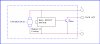
About the one driver + 3 fans combo ....
The schematic can be like that ..( ido not see any problem why it shouldn't work ...
But the trained & far more experienced eye of Guod, might be seeing something I've already missed or did not even know about ... )
One relay ,3x LM2907 ,one for each fan ...
At the zip folder ,the DipTrace pcb file for a single driver-single fan .
Cheers.
Attachments
-
16.5 KB Views: 7