Diy digital 4 light controller with timer

roidrage152

Active Member
side.jpgoutside open.jpg

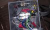
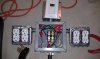
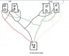
This is my DIY 4 1000w light controller with built in digital timer

I based this design on a few different ones I found on the web. The only original poster I know I can thank personally is Watercooled from THCFARMER.com. The Thread for his under $50 lighting controller is found here: http://www.thcfarmer.com/forums/f95/diy-4-8-light-controller-less-then-50-a-37987/

I know these tutorials are supposed to be step by step, but I wasn't sure if I was gonna finish this, so I don't have good pictures to get us the entire length of the way, but

I'll try to give as detailed of a description as possible. I'm sure I'll miss a bunch of stuff, but feel free to just ask.

My goal was to save a bit of money by doing this myself, but I did it more for fun. There are several places where I could have spent either more or less money, but just picked what I did either based on personal preference, or convenience.

*I am not am not even close to being an electrician. I've done a decent amount of basic household wireing, as well as wiring my grow room. While an electrician obviously wouldn't need a guide from me, I've personally learned alot from guides like this. Please don't mess with electricity unless you have a good understanding of how it works. IT CAN KILL YOU.

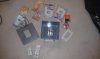
Here are the items I used:

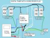
I installed a 40 amp (30 amp will do with the appropriate wire size) 220v 3 prong dryer vent. A 4 prong would work even better. A 40 amp dryer vent has the normal 240v, but also has built in a usuable 110v line. This 110v line is necessary if you want 110v controllers, or to properly wire the digital timer, which I basicaly did not do, but it seems to be working so far.

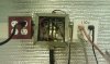
A contactor $35, similar to a relay. I bought mine at Grainger. I've seen these online and such for as low as around $20 each. I chose cause I could pick it up in a store. This is the only store I could find that actually had something like this on their shelves. I beleive this is a stock picture, my item looks slightly different. What you are looking for is "Compact Contactor, Definite Purpose, Full Load Amps-Inductive 30, Full Load Amps-Resistive 40, Number of Poles 2, Coil Volts 120VAC, 50/60 Hz, Non Reversing, Enclosure Type Open." They key points are 30 amp, 2 pole, and 120VAC.
http://www.grainger.com/Grainger/SQUARE-D-Compact-Contactor-5B126?Pid=search

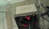
A Junction box. The one I used is PVC and is pretty much like this: about $14
http://www.homedepot.com/h_d1/N-5yc1v/R-202043436/h_d2/ProductDisplay?langId=-1&storeId=10051&catalogId=10053

2x 20 amp outlets. $6. To properly wire this, you would use 240v outlets. I used normal outlets, because thats what my ballasts have. Also I couldnt find them. Even commercially made controllers from the big hydro companies will use regular, or double tap outlets in their devices. Its not a big deal, just NEVER plug a 110 device into this controller, your device will fry.
http://www.homedepot.com/h_d1/N-5yc1v/R-202066701/h_d2/ProductDisplay?langId=-1&storeId=10051&catalogId=10053&superSkuId=202887019

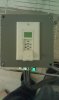
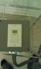
Digital Timer $27 - I used this model. There are simlar and cheaper ones, that have similar wiring schemes. It is a push button power switch, with timing controls under the little cover. I thougt it was a pretty neat item.
http://www.homedepot.com/h_d1/N-5yc1v/R-100685868/h_d2/ProductDisplay?langId=-1&storeId=10051&catalogId=10053

a length of 12 guage Romex wire. $13
http://www.homedepot.com/h_d1/N-5yc1v/R-202564826/h_d2/ProductDisplay?langId=-1&storeId=10051&catalogId=10053

a Dryer cord, rated for 30 amps or more. $19 I used this. You could save money by hard wiring your box. Just attach the bare wires that would go to the breaker to the spots where the dryer ends would go. I like the convenience of being able to unplug.

Fasteners $4. I used a combination of proper sized outlet screws (#6 - 32 threads per inch with appropriate sized bolts) and short wood screws. The wood screws were easier in the spots they would work, because bolts are hard to work with in the small area of the box.

Wirenuts, and crimp wire connectors. $6 you need the loop kind and the flatter kind. These go over the connections on the contactor, you would know them if you saw them. These are not the exact ones I used, but are the right shapes.
http://www.homedepot.com/h_d1/N-5yc1v/R-202523048/h_d2/ProductDisplay?langId=-1&storeId=10051&catalogId=10053
http://www.homedepot.com/h_d1/N-5yc1v/R-202522733/h_d2/ProductDisplay?langId=-1&storeId=10051&catalogId=10053

Outlet covers $2. I used the cheaper ones. For the timer you need the "decora" style rectagular opening faceplace.
 

Attachments

roidrage152

Active Member
inside.jpgstuff.jpgLC.jpg

The Colors are based on the color of the wires that I used. The red Triangles are wire nuts. For the connections to the Contactor, I used the crimp connections. 12G wire is a bitch to work with. I would probably use a bigger box if i did this again, so I would have more space. In fact I might even rewire everything into a bigger box later just so I can do maintenance checks on it from time to time to check security of connections. Everything got pretty crammed inside at the end.

I started by marking 2 rectangular holes on 2 sides of the junction box for mounting my outlets. I used a dremel saw to make the cuts. The cuts don't have to be perfect, each side will be covered by an outlet cover.

Now with a little room to get my fingers in the holes on the side, I drilled 2 holes in the back to mount my contactor. I secured 2 corners of the contactor with machine screws, a washer, and a bolt. The tiny bolt was hard to work with, that's why I only did 2, instead of mounting all 4 corners. There was a plastic dimple on the inside of my PVC box that kept the contactor from sitting perfectly flat, I pretty much just ignored this and mounted it at flat as it would go.

Then I stripped apart some of my 12/2 romex wire in the approximate lengths I needed. I kinda just eyeballed it, the best I can do is tell you to look at my diagram, and check out the lengths you will need. For each connection to the Contactor, I used crimp style connectors. The link at the top of my orignal post has super descriptive details on how a contactor works, so I'm not going to get into that.

I wired my outlets together, and then connected them to one side of the contactor.

I drilled a small hole in the bottom of my box, and put in a screw to attach my grounds too. I'm not really sure how adequate a screw in a plastic box is, but its what i did. I put a round crimp connection on the end of my ground, and help it on this screw with a bolt.

To connect the dryer plug, its so heavy, instead of using the crimp connectors, I actually took out the screws on the contactor and mounted the 2 big "LIVE" lines from the cord under the screws. The middle wire on this dryer cord which was a little skinnier is technically the ground, but this is where things get a bit tricky.

I was at first a bit confused trying to wire in the timer, but knew it had to be possible. Technically the timer wasnt built for this kind of set up, because it is a 110v device. Technically a 220v device is just 2 110v lines and a ground. I figured I would just use one of the 110v lines to power it. The trickiness is that there is no neutral in a 220v line. I used the ground from the Dryer line as my neutral for the timer. I beleive this is how old school stoves and dryers were before they changed the electrical codes to 4 wire. Also the connection here was awkward because the dryer cord had a ring on it. I basically wrapped a pigtailed wire from my timer's white line in the ring and taped it up. There is probably a much safer way to make this connection. Using a 4 wire dryer outlet would actually make alot more sense for this set-up. It would also allow room to add some 120v outlets that could be timed as well. The wiring involved in that is tricky, and would have to be on another post. If I ever get around to making one, I'll post some details or a diagram. If you ask about the details of that, I'll tell you what I think I know.

Connect each of the other timer wires as indicated on the diagram (The red just gets a cap, it is not used in this setup). I tested mine out a bit before putting the cover on, but once you make all the proper connections, I'd put all the covers on and give it a test run by plugging it into the dryer outlet. Before the timer is programmed, the timer itself also acts as a power switch. Just press the button and it should activate/deactivate your Contactor. When active juice is going to the outlets on the side of the box. My contactor made a small humming noise when active. I'm not sure if that is normal or not because this is my first time using one. But as a test, I just plugged a stand alone 16g power cord into my contactor without all of the other questionable wiring, and it made the same buzzing. So I am gonna go with the guess that this is normal.

Please feel free to ask any questions, I'll make alterations to this if I see anything I missed. Please keep in mind again, I'm not an electrician, I'm sure I'm going to get flamed alot for even posting this. If people give warnings about any dangers associated with making this, make sure you listen to what people have to say, they are probably right. All the things that people tell you that are wrong with my design, can help you make an even better design. My next couple things I will be messing with is some temperature controllers I think. If I come up with anything good, I'll post it. Remember again, BE CAREFUL, Electricity is dangerous. Double and triple check all connections, and that you are not handling any live wires. Also remember, this is a 220v controller, plugging 110v devices into it, even though they fit is VERY bad news. I think it would be guaranteed death for that device, and probably some smoke and sparks and stuff. No Bueno.
 

roidrage152

Active Member
That thing is sweet man. How hard is it to cut those boxes? I was planning to copy This diy http://howtobuildagrowroom.com/Hydroponics/index.php/9-diy-hydroponics/68-diylightingcontroller?showall=1&limitstart= Then add a high temp shut off for the summer months, I only need 4 plugs and I like the clean look of your box.
I have a dremel Multimax which makes it pretty easy, I dont know any other tools well suited. Maybe a regular dremel type tool to plunge cut. Take your time because they heat makes the edges melty. The plastic is pretty tough I duno that any non power tool would be practical. I'm actually pretty OCD so I scrapped mine and re did a 4 wire line. In the process I switched to a metal box and added 4 110v timed outlets. I'll post a pic and the wiring diagram tomorrow probably. I don't really see any issue with the 3 wire set up, it's actually pretty common practice to add 110v this way. anyone with and older house with and old dryer or stove is probably wired this way.

The benefit of DIY would be to either save money or build a superior product. I did use some higher quality parts than the hydro companies do but I overspent.

If I wanted to go cheaper I would build the cheap $50 design then add the proper safety features.

I would definitely enclose the contactor. There is probably a deep junction box it would fit in and you can screw a cover on.

Use 12 gauge wire with 20 amp outlets.

Use a 4 wire dryer type run if you want timed 110v outlets. (diagram to follow).

The run itself to the breaker box can be expensive because the higher gauge wire is expensive. For a 30 amp breaker u need minimum 10g wire. 15 feet of 10/3 romex (3 +ground) is $30 dollars. My outlet is like 4 feet from my breaker box and I needed every inch of that 15 feet to get up and around my studs. If u step up to 40/50 amps 8 or 6g wire, you are over $50 for even the shortest run. However at that size you can run a pretty big grow from 1 outlet.

Hard wiring the box can save some money. The dryer outlet is about $9 and the dryer cord is about $22. Just a side note I used a 50 amp outlet and cord because the price diff was negligible and gives me room for significant upgrade without that $40 expense next time.

Here is another thing that should help ppl I learned a while back from a home depot guy, it's the formula to calculate how many amps ur pulling on a circuit.

Watts / volts = amps

So imagine a set up with 4 1000w bulbs. At 240v it pulls

4000/240=16.7

That would be a little over half the load. I think the max recommended is 80% but I think there is another rule for stuff that stays on more thN like 3 hours at a time that says stay under 70%. I think the ballasts might pull a few amps separately though. Like I've previously stated I barely an amateur electrician so don't quote me. I always err waaayy on the side of caution.

Remember also I'm really afraid someone is gonna fry something Only 240v devices into this design. Im really afraid someone is gonna try to put their fan on this or something and at best fry their fan or and worst get hurt or something. gonna try to put up the combo design tomorrow.
 

roidrage152

Active Member
Again I want to place the warning that people need to be careful if trying to use one of these. I would feel bad if I would be providing wiring diagrams and people with no knowledge or respect for the danger involved in working with electricity were to get hurt. To be as safe as possible I used wire nuts, crimp connectors, or splices for all of my connections. I would recommend this to you as well for the safest connections possible. These are very cheap items.

Please remember to use 110v devices with the 110v outlets, and 220v devices with the corresponding 220v outlets. This is a very important safety issue. On my version I actually spray painted the 220v side red, and will do the same for the face plate when I put it on. I'll also clearly label the voltage on the face plate. I cannot stress the importance of this enough.

I scrapped my last one and re-wired it with a 4 wire dryer outlet. I also used metal boxes.

The set-up I used has 4 timed 110v outlets and 4 timed 240v outlets, controlled by a digital wall timer. For all of the wiring I used 12g wire safe for up to 20 amps, but I used 15 amp outlets for my 110v outlets, just so they would look different and they are cheaper. These things come in various colors too, so you could color code your design.

I haven't gotten the face plates yet, Home Depot was out of the sizes I needed when I bought this stuff.

The box I used is just a junction box I bought from Home Depot, I believe it is 8"x8"x4". You can use pretty much any kind of boxes for the contactor and the outlets, this is a personal cosmetic and safety preference. Everything is from Home Depot but the contactor. I connected the outlet boxes to my main box with Romex clamps, but you could probably just attached them directly with screws.

With the 4 wire 220v line you can use any combination of timed or non-timed 220v or 110v outlets up to the available amps. There is just minor changes needed to the wiring. I put the calculation in the post above this one to calculate how many amps your devices are pulling. I'll use this run to operate 4 1000w lights, 2 inline fans, and have 2 outlets available for later.

lc2 DIAGRAM.jpg

Let me know if you have any questions about the wiring layout.


PIC LC2.jpg

I plan to use regular nylon face plates for the outlets, and will label them with proper voltages. The main box has a plain metal cover.
 
There is probably a deep junction box it would fit in and you can screw a cover on. There is probably a deep junction box it would fit in and you can screw a cover on.


TruenoAE86coupe

Moderator
Looks awesome, i was wondering if any one else here used contactors....
Mine certainly isn't as good looking as yours, but i use an ugly version of this, and there is nothing better! I love being able to have my timer wherever i want it and only have to have a trigger wire from it to the contactor, works very well with my ballasts being outside the room, timer is still in so i can check it everyday.
 

craftymofo

Active Member
Contactors are awesome for doing what we do. A hell of a lot safer than solid state relays. It is crazy how much cheaper a DIY of this is over the premade options out there
 
Again I want to place the warning that people need to be careful if trying to use one of these. I would feel bad if I would be providing wiring diagrams and people with no knowledge or respect for the danger involved in working with electricity were to get hurt. To be as safe as possible I used wire nuts, crimp connectors, or splices for all of my connections. I would recommend this to you as well for the safest connections possible. These are very cheap items.

Please remember to use 110v devices with the 110v outlets, and 220v devices with the corresponding 220v outlets. This is a very important safety issue. On my version I actually spray painted the 220v side red, and will do the same for the face plate when I put it on. I'll also clearly label the voltage on the face plate. I cannot stress the importance of this enough.

I scrapped my last one and re-wired it with a 4 wire dryer outlet. I also used metal boxes.

The set-up I used has 4 timed 110v outlets and 4 timed 240v outlets, controlled by a digital wall timer. For all of the wiring I used 12g wire safe for up to 20 amps, but I used 15 amp outlets for my 110v outlets, just so they would look different and they are cheaper. These things come in various colors too, so you could color code your design.

I haven't gotten the face plates yet, Home Depot was out of the sizes I needed when I bought this stuff.

The box I used is just a junction box I bought from Home Depot, I believe it is 8"x8"x4". You can use pretty much any kind of boxes for the contactor and the outlets, this is a personal cosmetic and safety preference. Everything is from Home Depot but the contactor. I connected the outlet boxes to my main box with Romex clamps, but you could probably just attached them directly with screws.

With the 4 wire 220v line you can use any combination of timed or non-timed 220v or 110v outlets up to the available amps. There is just minor changes needed to the wiring. I put the calculation in the post above this one to calculate how many amps your devices are pulling. I'll use this run to operate 4 1000w lights, 2 inline fans, and have 2 outlets available for later.

View attachment 1921291

Let me know if you have any questions about the wiring layout.


View attachment 1921290

I plan to use regular nylon face plates for the outlets, and will label them with proper voltages. The main box has a plain metal cover.
my dryer is plugged into a regular wall socket which has a single 20amp breaker in the box. Just above the wall socket, I have a 4plug dryer outlet which has a quad pole 30amp in the middle an 20amp on outer breaker in the box. Would your set up work well for me even though I just plan to run 2 1000w an maybe add a 3rd light later? Thanks in advance.
 

craftymofo

Active Member
my dryer is plugged into a regular wall socket which has a single 20amp breaker in the box. Just above the wall socket, I have a 4plug dryer outlet which has a quad pole 30amp in the middle an 20amp on outer breaker in the box. Would your set up work well for me even though I just plan to run 2 1000w an maybe add a 3rd light later? Thanks in advance.
That is very odd. Is it a 240 or 120 breaker. As long as it is 240 your current would be safe. If it is 120 you would be right at the limit. Above the limit if it where my set up as I, like most don't like to go above 75-80% of rated amperage. I would imagine it is a 240v breaker, but the fact it is only a 20 would have me wonder the quality of work the electrician did.
 

roidrage152

Active Member
"I have a 4plug dryer outlet which has a quad pole 30amp in the middle an 20amp on outer breaker in the box."

I'm not sure what you mean by this. I'm no electrician and I don't know all the proper terminology myself, but I'm having trouble picturing the setup.

If I understand, I think you mean your 4 plug dryer outlet goes to a TWO pole 30 amp breaker in the box. Meaning, the breaker on one your box looks like 2 normal breaker connected to one lever. That would absolutely work with this set up, but just make sure you know for sure that is how it is set up. The way you explained it is kinda confusing and makes me worried someone jimmy rigged a 4 wire outlet into your breaker box or something.
 

craftymofo

Active Member
Sorry to confuse you. This should work for you then. I had a place like that once that set up so I could have either a gas or electric dryer. Just odd to only have 20A in the breaker.
 

roidrage152

Active Member
Forgot I posted this, I actually ran into an issue with the digital timer I used in this description. I chose it because I thought it was more pro looking and cooler than pin models, or just using a cord attached to a seperate timer. The problem with this digital timer is that if the power goes out, even briefly, it doesn't verify if it was supposed to be On or Off when the power is restored, and won't turn back on until the next time in it's saved cycle that it was supposed to be turned on. My remedy was just just replace the timer with a cord that goes to an external timer. Another option would be to use a "pin" style wall timer, that would recognize if it supposed to be on or off in the event of a brief power outage. Feel free to post if you have any questions, I'll try to answer as best I can.
 

ilikecheetoes

Well-Known Member
Again I want to place the warning that people need to be careful if trying to use one of these. I would feel bad if I would be providing wiring diagrams and people with no knowledge or respect for the danger involved in working with electricity were to get hurt. To be as safe as possible I used wire nuts, crimp connectors, or splices for all of my connections. I would recommend this to you as well for the safest connections possible. These are very cheap items.

Please remember to use 110v devices with the 110v outlets, and 220v devices with the corresponding 220v outlets. This is a very important safety issue. On my version I actually spray painted the 220v side red, and will do the same for the face plate when I put it on. I'll also clearly label the voltage on the face plate. I cannot stress the importance of this enough.

I scrapped my last one and re-wired it with a 4 wire dryer outlet. I also used metal boxes.

The set-up I used has 4 timed 110v outlets and 4 timed 240v outlets, controlled by a digital wall timer. For all of the wiring I used 12g wire safe for up to 20 amps, but I used 15 amp outlets for my 110v outlets, just so they would look different and they are cheaper. These things come in various colors too, so you could color code your design.

I haven't gotten the face plates yet, Home Depot was out of the sizes I needed when I bought this stuff.

The box I used is just a junction box I bought from Home Depot, I believe it is 8"x8"x4". You can use pretty much any kind of boxes for the contactor and the outlets, this is a personal cosmetic and safety preference. Everything is from Home Depot but the contactor. I connected the outlet boxes to my main box with Romex clamps, but you could probably just attached them directly with screws.

With the 4 wire 220v line you can use any combination of timed or non-timed 220v or 110v outlets up to the available amps. There is just minor changes needed to the wiring. I put the calculation in the post above this one to calculate how many amps your devices are pulling. I'll use this run to operate 4 1000w lights, 2 inline fans, and have 2 outlets available for later.

View attachment 1921291

Let me know if you have any questions about the wiring layout.


View attachment 1921290

I plan to use regular nylon face plates for the outlets, and will label them with proper voltages. The main box has a plain metal cover.
In your first hitech AutoCad schematic above ;) I cant tell how the 240/120 are any different. They both have a white/black/green connection. I would have thought the 240 would have 2 white or black or something different than the 120. Or is that done on the contactor? I've read this 3 times but keep fading out due to lack of pics and colors. lol.
I also notice you updated it about the timer not saving its settings. Im suprised it doesnt have some kind of battery or ram to save that info. oh well the big mechanical timers look cool too.
 

roidrage152

Active Member
I have changed this design as mentioned above to eliminate the digital timer as the timer didn't work out for me. That being said I'll actually make a new drawing for u and clearer description shortly.

But main difference is in that 220 runs with 2 live wires 1 ground. 110v has 1 live and 1 neutral and a ground green.

For a 3 wire (3 prong) dryer outlet you should not run any 110v outlets.

With a 4 wire (4 prong) dryer plug, in addition to the normal BLACK, WHITE, GREEN, is an addition wire RED. In this configuration, RED and BLACK are both live, WHITE is a neutral, and GREEN a ground. The WHITE wire would only be used in a situation where you will be wanting 110v outlets. This WHITE wire was added to dryer cords in order to power 110v accessories on modern 220v devices, such as digital clocks and such on a stove.

*A side note, I use the terms 110v/120v, 220v/240v interchangable. For our purposes 110v and 120v are the same, and 220v and 240v are the same.

The biggest confusing thing to me was how to make 110v and 220v happen at the same time in 1 controller. If your needs are for 220v only, or 110v only, the wiring is far simpler.
 

roidrage152

Active Member
AS ALWAYS PLEASE USE COMMON SENSE WHEN DOING ELECTRICAL WORK. QUADRUPLE CHECK EVERYTHING. PLEASE ASK QUESTIONS.

As Long as I am active I will be happy to answer any questions that anyone has regarding my design. I qualify again, I am not a licensed electrician. I have been using this current design for several months now without issue. Please be safe, I provide these diagrams because I wish I could have found something like this when I was trying to figure out this design.

Just as a recap:
-For my contactor, the best price I find now is about $11 on eBay. (FULL LOAD 30 amp, 120v, definite purpose contactor)
-I used a 30 amp+ rated 4 prong dryer cable
-plugged into a 30 amp dryer outlet
-wired to a 30 amp 220v breaker

-The 3 prong outlets I used on both the 110v and 220v sides are 20 amp rated
-I used 12 guage wire throughout.

-For the plug that goes to your timer, pretty much any lamp cord will do. An old PC/monitor cable stripped will do as well. Just use the proper connections.
wire1.jpg

simplified.jpgpic.jpg
 

ilikecheetoes

Well-Known Member
Capture.JPG
OK let me take the timer/relay out of the loop just so I can be triple positive I got you. This look right? Obviously the yellowish is the white wire.

And this is my badly sketched final idea. I want 2 120s on the timer and 2 off. There's got to be something better than paint for this ;) i need to dig out my visio. I think may have a relay laying around here somewhere from another progect that didnt quite make it. Home depot gift cards will get a workout tomorrow.
Cap2.jpg

I liked watercooleds idea with the light switches. But I thought circuit breakers will look cooler. ;) I went ahead and put in the time delay and thermal cutoffs as well. With 6 lights I can spread them around enough so that theres at least some light even if it starts cooking and 4 lights turn off.
 
Top