ilikecheetoes
Well-Known Member

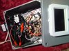
i dont like the ground mounted right on the board but I left it until my buddy can tell me what to do with it.
i assume that was pointed to me? You obviously didnt check out the site. Its a environment controller using some relays and sensors. No scary exposed wire high voltage. Furthermore the project is dead, mainly because i lost interest in it. I do that a lotNot to come out wrong but I think this could be considered a textbook case of negligence should god forbid something end up happening. Also should Leo come knocking about they would love showing that image in court. On top of anything else you have a post to your site where you are asking people to beta test your products for just slightly less than what a tested know working system would cost you. If this is where you get after dropping over 300 bucks on this set up I can only imagine how solid your controller is.
What? I'm using T101's as timers alreay, but each one power's one outlet, which one ballast runs off of.... I have 120v power running to my timer's. I don't see what you are getting at, as I dont see how a guy would hook 4 or 5 ballasts up to one T101? I have room in my panel for another double pole breaker (240), so what, if anything can I do with 1 T101 to power multiple ballasts at once? am i missing something??Here is the schematic for the T-101 http://www.intermatic.com/~/media/Intermatic/Documentation/Time%20Switches/Mechanical%20Time%20Switches/24%20Hour/T100%20Series/T101%20Instructions.ashx In my opinion it would be even easier to hook this up than the ones on here.
From your power in hook up the green wire to ground, white to neutral, and black to the line inputs. If you are hard wiring you lights to the timer you will connect the green(ground) to the ground screw, white (neutral) to screw A, and tho a little confusing looks like the black(line) wire to screw 2. If you are going to run it to a box with outlet they are labled as to what wire goes where. I assume you are going to be using 240? if not it would not be able to handle the load at 120.