Dealing with fan failure

Positivity

Well-Known Member
I swear that was bugging the sh@t out of me. Too much herb sometimes.

When i first initially was figuring out how to wire them i almost put it on the dc end. My lights are wired with them on the ac end of the driver. Switch on the line and thermostat on the neutral. Ammeter is wired in series with the cob. Helloooo...

Thats why i like cases too, so i can fit stuff in like that, with one cord running out.

Also why i don't give electrical advice usually. But i like the thermostat soooo. I'm a case study in persistance...:-P. I figure it out as i go and sometimes mix up these details if i haven't done it in a little while.

:peace: :joint: 
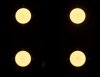
Might have to turn the uvb down..
 
Last edited:

Rahz

Well-Known Member
I was looking at the link and the switch is rated

16A 125V AC (Resistive Load)
10A 250V AC (Resistive Load)

So it could be used on the AC side right?

Some companies are paying attention.

http://shop.stevesleds.com/Thermal-Switch-Overheating-Protection-8794102497.htm

I put them on all of my cpu/led coolers. Simply add it inline, after the cob. The circuit will open and the led will shutoff at the rated temperature. Thermal adhesive it somewhere it will fit and screw it down so it dosen't get knocked off. I have some pictures somewhere in my thread..

Also a good idea to use insulated quick connects and a little liquid electric tape on the exposed connections to isolate everything
 

Positivity

Well-Known Member
I was looking at the link and the switch is rated

16A 125V AC (Resistive Load)
10A 250V AC (Resistive Load)

So it could be used on the AC side right?
I believe so, as long as the driver is within 16A.

Are you going to put everything in an enclosure?

Not sure i'd want to run the AC line to a remote cob. I've used them a few different ways but the thermostat and wiring is always in a enclosure.
 

Rahz

Well-Known Member
Yes an enclosure will be housing everything. Single driver running 4 cobs in parallel is what I have in mind for my next project so it would have to be on the AC side unless I used one for each COB.

I've been talking to a metal worker who is going to build me a custom enclosure. LED agro lights has become a hobby in my hobby and it's taking over! Ferts and strains, blah blah blah... let's build lamps!
 

stardustsailor

Well-Known Member
Now...
For those not so capable in electronics ,but willing to spend few bucks more ...
There's this option ...

To use an Arduino Uno REv.3 board, the Rocketscream Reflow Oven Controller shield ,
a K type thermocouple and a modified sketch ...

Usually I use this "combo " for testing the cooling system ..

For example :

With an ambient temp of ~18°C
P3252543.JPG

And placing the thermocouple's tip with some Kapton tape at the Tc measuring spot of Vero 29
P3252542.JPG

At 1530mA ...
P3252540.JPG

In order not to get blinded while working,I've placed over the cobs ,a piece of welding mask glass ..
But ,the Veros had different opinion about that ...
P3252537.JPG

Anyway ...The heat over the LES is quite high ..
P3252533.JPG
(^^^pic taken with a Grey Neutral Density x8 filter ,placed at the camera lens )

P3252529.JPG

Cheers.
:peace:
 

stardustsailor

Well-Known Member
Parts list -Hardware :

-Arduino Uno rev3.
http://arduino.cc/en/main/arduinoBoardUno

-Rocketscream Reflow Oven Controller Shield for Arduino Uno.
http://www.rocketscream.com/shop/reflow-oven-controller-shield-arduino-compatible

( This arduino shield features : 2x8 blue/white LCD screen ,SSR relay output ,RED led ,two push button switches ,K type thermocouple input & MAX31855 thermocouple amplifier IC ,Buzzer ,LCD screen contrast adjust ,LED/Button Switch extension pins & reset button switch )

-Glass braided K type thermocouple
http://www.adafruit.com/products/270

-SSR relay (40 A )
https://www.sparkfun.com/products/13015
 
Last edited:

stardustsailor

Well-Known Member
Software :
-MAX31855 Library for Arduino (Freeware )
https://github.com/rocketscream/MAX31855

(Far right at page ,"Download ZIP " ,Unzip file & name it "MAX31855",then drop the unzipped file onto C/ Program files/Arduino/Libraries)

-Arduino IDE software (Freeware )
http://arduino.cc/en/main/software

-Copy ,paste at Arduino IDE ,save as xxxx.ino &
upload on the Arduino the code (sketch ) written at the next post
.
 
Last edited:

stardustsailor

Well-Known Member
Sketch :

//
//Thermocouple Type K Temperature Check & SSR Control
//2015 by SDS
//
//**LIBR**
#include <LiquidCrystal.h>
#include <MAX31855.h>
// ***** DEGREE SYMBOL FOR LCD *****
unsigned char degree[8] = {
140,146,146,140,128,128,128,128};
// ** PIN ASSIGNMENT **
int ssrPin = 5;
int thermocoupleSOPin = A3;
int thermocoupleCSPin = A2;
int thermocoupleCLKPin = A1;
int lcdRsPin = 7;
int lcdEPin = 8;
int lcdD4Pin = 9;
int lcdD5Pin = 10;
int lcdD6Pin = 11;
int lcdD7Pin = 12;
int ledRedPin = 4;
int buzzerPin = 6;
int switchPin = A0;
//**Variables-Constants**
unsigned long nextCheck;
unsigned long nextRead;
double input;
#define SENSOR_SAMPLING_TIME 250
//**INTERFACE**
LiquidCrystal lcd(lcdRsPin, lcdEPin, lcdD4Pin, lcdD5Pin, lcdD6Pin, lcdD7Pin);
MAX31855 thermocouple(thermocoupleSOPin, thermocoupleCSPin,thermocoupleCLKPin);
//
//**SET-UP**
void setup()
{
// SSR pin initialization
digitalWrite(ssrPin, LOW);
pinMode(ssrPin, OUTPUT);
// Buzzer pin initialization - buzzer off
digitalWrite(buzzerPin, LOW);
pinMode(buzzerPin, OUTPUT);
// LED pins initialization -turn on upon start-up (active low)
digitalWrite(ledRedPin, LOW);
pinMode(ledRedPin, OUTPUT);
// Start-up splash screen
digitalWrite(buzzerPin, HIGH);
lcd.begin(8, 2);
lcd.createChar(0, degree);
lcd.clear();
lcd.print("Type_Ktc");
lcd.setCursor(0, 1);
lcd.print("SDS_2015");
digitalWrite(buzzerPin, LOW);
delay(2500);
lcd.clear();
// Turn off LED (active low)
digitalWrite(ledRedPin, HIGH);
// **Initialize time keeping**
nextCheck = millis();
// **Initialize thermocouple reading **
nextRead = millis();
}
//
//**Loop**
//
void loop()
{
//** Current time**
unsigned long now;
// ** read thermocouple**
if (millis() > nextRead)
{
// ** next sample**
nextRead += SENSOR_SAMPLING_TIME;
// **Read current temperature**
input = thermocouple.readThermocouple(CELSIUS);
}
if (millis() > nextCheck)
{
// **Check input **
nextCheck += 250;
// **LCD**
lcd.clear();
lcd.print("Reading:");
lcd.setCursor(0, 1);
// **Show current temperature**
lcd.print(input);
#if ARDUINO >= 100
lcd.write((uint8_t)0);
#else
lcd.print(0, BYTE);
#endif
lcd.print("C ");
// **If thermocouple problem is detected**
if((input == FAULT_OPEN) || (input == FAULT_SHORT_GND) || (input == FAULT_SHORT_VCC))
{
lcd.clear();
lcd.print("Caution:");
lcd.setCursor(0, 1);
lcd.print("Error!");
digitalWrite(buzzerPin, HIGH);
delay (500);
digitalWrite(buzzerPin, LOW);
delay(2000);
}
}
//**SSR directive**(65°C Threshold)
if (input >=65)
{
digitalWrite(ssrPin, HIGH);
digitalWrite(buzzerPin, HIGH);
digitalWrite(ledRedPin, LOW);
delay (500);
digitalWrite(buzzerPin, LOW);
delay(500);
}
else
if (input < 65)
{
digitalWrite(ssrPin,LOW);
digitalWrite(buzzerPin,LOW);
digitalWrite(ledRedPin,HIGH);
}
//**Loop end**
}
//End
 
Last edited:

stardustsailor

Well-Known Member
Now ..
This Arduino " COB Case /Heat sink temperature measuring and SSR relay Thermostat features :

-Type K Thermocouple "Not-connected & Short circuit " buzzer alarm and LCD
screen ERROR notification.


-Sampling every 250 millisecond ( 4 samples per second ) .
***** You can change this sampling rate value at those lines :
" #define SENSOR_SAMPLING_TIME 250 " and " nextCheck += 250 ; "

- Optical (red LED ) and buzzer alarm ,if COB case / heat sink exceeds 65°C .

***** You can change this threshold value at those lines :
" if (input >=65) " and " if (input < 65) "

-Solid State Relay ( <= NC type = Normally closed ) Control ,
with Red LED signaling and buzzer alarm ,when temperature exceeds pre-selected temperature threshold (Default =65°C )


Cheers.
:peace:
 
Last edited:

stardustsailor

Well-Known Member
Thank you so much @stardustsailor. When you first showed us this in your original build thread I was a bit lost. I have never dabbled in arduinos. But this is very clear and near idiot proof.
Let the games begin
Very-very easy to do .
Just need few -more than few actually- bucks more ,than the analog electronic option .
But it'is worth them ,all the way ..
Just let me design the connections ,also .
 
Last edited:

Positivity

Well-Known Member
If i keep looking at this enough times i should begin to understand the code...lol

In all fairness i haven't even attempted it yet though. Can't do anything myself until i get a new puter'. The new mac is so tempting but i've got other big purchases i need to make first
 

stardustsailor

Well-Known Member
CAUTION !!!!


In case of a Normally Open (NO ) Solid State Relay is used ,then the following lines of the code :

- // SSR pin initialization
digitalWrite(ssrPin, LOW);


and ...

- //**SSR directive**(65°C Threshold)
if (input >=65)
{
digitalWrite(ssrPin, HIGH);


and ...


-
if (input < 65)
{
digitalWrite(ssrPin,LOW);


Must be changed to :


- // SSR pin initialization
digitalWrite(ssrPin, HIGH);


and ...

- //**SSR directive**(65°C Threshold)
if (input >=65)
{
digitalWrite(ssrPin, LOW);


and ...

-
if (input < 65)
{
digitalWrite(ssrPin,HIGH);


Cheers.
:peace:
 

stardustsailor

Well-Known Member
I've been looking at these things you do, I'm starting to get a little confidents in myself. I'll think a little more before I try it, Great teaching thread though. You make everything look so easy.
It is very easy ,actually ..
And there are some pins left unused ,as also the buttons.
They can be used to connect a pot and adjust the threshold value , "on-the-fly"..
But it needs a bit more of code .
If anyone interested about this "Tc /Ths limit on-the-fly pot adjust " just let me know .
I'll post the needed parts,wiring and code for this "enhancement" ..


Right now,I'm kinda tired or bored ,I guess ...
Or is it that "moonshine" I've been drinking along with my favourite white russian ?
-Prone to abuse,I know all about it ...

LOL!
P3262546.JPG


Ohhh.. ..(burp ! ) ...
Feelin' F@(k|n' Great ...


Cheers.
:peace:
 
Last edited:

stardustsailor

Well-Known Member
@stardustsailor

What do you think about this thermal plug from Jee Labs....
http://www.digitalsmarties.net/products/thermo-plug

I like the reflow oven kit, that is badass, but the JL is toned down a bit more.... This whole thermalcouple project is my next endeavor...just received my 5110 screen finally and can start working on this and PAR meter :peace:
Compared ( price -wise) to the Reflow oven shield ,I'd prefer the shield .
(It has it's own LCD screen and headers included ,plus a transistor controlled SSR output / Buzzer,
plus the super -accurate /precise & fast MAX31855 chip )

( For cheap LCD 5110,next time , check here:
http://www.exp-tech.de/nokia-5110-lcd
My favourite graphic screen ..I've even made my own library for it ,using just three pins from Arduino ..)
P3262547.JPG


Have you found a -relatively - cheap PAR sensor ? Where ?


Cheers.
:peace:
 
Last edited:

stardustsailor

Well-Known Member
@stardustsailor how would you hook up multiple thermocouples to monitor multiple cobs?
And would that require some code alteration?
For multiple COB monitoring ,thermocouples are quite expensive option.

A cheaper solution, is to use NTCs ( negative coefficient thermistors ).
But then another-totally different and more complicated- code is needed...
And more advanced skills at electronics,for sure ..
Check here:
https://www.rollitup.org/t/diy-cree-cxa-arduino-thermal-monitoring-protection.824070/

Cheers.
:peace:
 
Last edited:
Top