dandyrandy
Well-Known Member
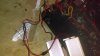
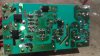
The 0 ohm components or fuses each go back to one of the bridges. The go to the switching transformer primary circuit. One probably actually goes to a switching transistor then to the transformer. The line looks like it should go to both. Possibly it's for Daisy chaining?