iHearAll
Well-Known Member
What youll need,
-4ct: 100w LEDs that use a voltage between 30-36v and draw about 3-3.5A at max power.
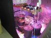
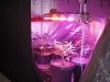
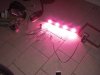
You won't be powering them this hot. You'll be powering them between 2-3A to preserve the life of the LEDs and not cook up your grow room in heat. I'm using some blurple EPISTARs here. But you could use 4ct whites or blues, or 6ct Reds if they're 20-26v
-small tube of thermal paste or silicone grease
-1ct: full wave bridge rectifier that can handle at least 200v and 6 amps to play it safe. these only cost about $1.50 on ebay (part# sk10254 is what im using here)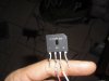
-1ct: 200uF AC Capacitor rated for a minimum of 125VAC. $2.50 on ebay literally just type in "200uF AC capacitor" DO NOT USE A DC CAPACITOR (for this at least.)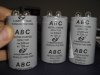
-1ct: 3.5A fast blo fuse, just get 10 to have them handy if you muck something up. do all your testing with a fuse in place so you dont burn out a 35$ LED. 10ct fuses on ebay are about $2.50.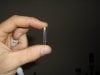
-1ct: Fuse holder, these are $2.25 on ebay. they're just two electrodes that clamp a fuse in place and make for easy fuse replacing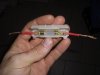
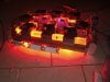
-Enough heat control, this cost is on you. i gutted a poor ol' car amplifier for the two large heatsinks, i still need to add pc fans to keep it cooler. theyre in the mail right now.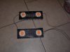
-Red/Black hookup wire if you have it around. you can easily use any color just get solid core 16awg there-abouts
-Light switch... 69 cents at lowes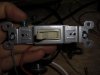
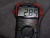
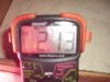
-Multimeter with a DC current setting
-solder/soldering iron
-damp paper towel
-AC cord with a ground plug that fits an outlet. the ground plug isn't actually necessary but helps maintain the location of the HOT terminal in the cord. The HOT terminal is the smaller of the two flat plugs. The NEUTRAL is the larger. GROUND is the circular plug part that tends to break off when fucking around.
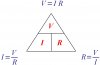
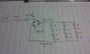
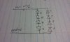
So, let's build it.
Im purposefully not going into any detail other than a schematic because i do not want those uneducated in electricity to start here because they want to grow some dope for cheaper. Just buy a meanwell ballast if you dont know what your doing with a schematic. this one is is really easy to follow. just put the fuse on either the Hot or the Neutral wire, it really doesn't matter which but will protect your circuit during testing and if lightning strikes your power lines.
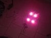
 ewww blurry
btw the 20$ limit is the ballast cost, not the LEDs and heatsinks. fyi
-4ct: 100w LEDs that use a voltage between 30-36v and draw about 3-3.5A at max power.
You won't be powering them this hot. You'll be powering them between 2-3A to preserve the life of the LEDs and not cook up your grow room in heat. I'm using some blurple EPISTARs here. But you could use 4ct whites or blues, or 6ct Reds if they're 20-26v
-small tube of thermal paste or silicone grease
-1ct: full wave bridge rectifier that can handle at least 200v and 6 amps to play it safe. these only cost about $1.50 on ebay (part# sk10254 is what im using here)
-1ct: 200uF AC Capacitor rated for a minimum of 125VAC. $2.50 on ebay literally just type in "200uF AC capacitor" DO NOT USE A DC CAPACITOR (for this at least.)
-1ct: 3.5A fast blo fuse, just get 10 to have them handy if you muck something up. do all your testing with a fuse in place so you dont burn out a 35$ LED. 10ct fuses on ebay are about $2.50.
-1ct: Fuse holder, these are $2.25 on ebay. they're just two electrodes that clamp a fuse in place and make for easy fuse replacing
-Enough heat control, this cost is on you. i gutted a poor ol' car amplifier for the two large heatsinks, i still need to add pc fans to keep it cooler. theyre in the mail right now.
-Red/Black hookup wire if you have it around. you can easily use any color just get solid core 16awg there-abouts
-Light switch... 69 cents at lowes
-Multimeter with a DC current setting
-solder/soldering iron
-damp paper towel
-AC cord with a ground plug that fits an outlet. the ground plug isn't actually necessary but helps maintain the location of the HOT terminal in the cord. The HOT terminal is the smaller of the two flat plugs. The NEUTRAL is the larger. GROUND is the circular plug part that tends to break off when fucking around.
So, let's build it.
Im purposefully not going into any detail other than a schematic because i do not want those uneducated in electricity to start here because they want to grow some dope for cheaper. Just buy a meanwell ballast if you dont know what your doing with a schematic. this one is is really easy to follow. just put the fuse on either the Hot or the Neutral wire, it really doesn't matter which but will protect your circuit during testing and if lightning strikes your power lines.
ewww blurrybtw the 20$ limit is the ballast cost, not the LEDs and heatsinks. fyi