crazyc123
Member
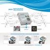
like i said i have purchased a Sentinel GPS HPLC-8T High Power Lighting Controller 8 Outlet with Integrated TimerI time the lights using a digital timer and $5 relays, one relay per 1/kw HID. The timer is used to activate the 12/vdc source that activates the relay(s). The relays switch the HID's on the HOT side or in some countries, the black wire. Never switch on the common/gnd side or white wire, in some countries. Each relay is equipped with a 15 amp bypass switch that I can use to switch on the HID'(s) manually in the event of a sub circuit circuit failure.
>>>>>>>> Common wall plug in timers and HID's do not mix well directly. <<<<<<<<
If what you've just read makes no sense to you, get a timer that is meant for HID lighting.
240 volt with 40 amp (2x20amp) built in circuit breaker running off heavy Orange 10 AWG and ETL listed to UL 508 STD for commercial use. figured that would be best thing out there.