Hi guys,
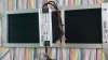
I need some help with this driver. I have two kits from KingBright of QB288s. Each kit comes with a heatsink, this driver, 2 x qb288 boards and a potentiometer. Plus all wires and connectors.
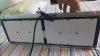
I assembled one kit and the potentiometer was working perfect. However because KingBright does not seem to care that there are no holes on their heatsink to mount the driver I have had to build an aluminium frame to mount all together.
After I mounted everything on the frame and started testing the potentiometer did not work. The lights just stayed at their highest brightness consuming 265W. With the potentiometer working the lowest was about 20W and the highest was 265W.
At first I thought I just broke something in the potentiometer while putting all together so I took another potentiometer from the second kit to test. I did not mount it on the frame first and just swapped dimming wires coming from the driver to the second potentiometer. With the second one dimming started working.
So I thought that the first potentiometer was faulty and I put the second one instead of it. After I assembled everything again the second potentiometer stopped working too. It does not exactly the same as the first one staying at this highest 265W and it does not react on me turning its knob.
After I tried to test with the driver from another kit neither of these two potentiometers was working at all.
Actually the both lights will turn on and stay at their highest 265W consumption even if I do not connect any potentiometer.
Both potentiometers seems to work when I test them with a multimeter.
It looks to me now that both potentiometers are ok but now there is something wrong with each driver. Even though dimming worked initially on either of this driver now it is not working.
I am not really good with electrical stuff, only basic things but considering that both drivers turn lights on even with dimming wires not connected to anything make me scratch my head. Looks like they became shortened inside the driver and simply do not react to a potentiometer.
Any ideas of what can be wrong?
I can leave with the boards getting 265W but I'd rather try to fix it so I can control the brightness .
I need some help with this driver. I have two kits from KingBright of QB288s. Each kit comes with a heatsink, this driver, 2 x qb288 boards and a potentiometer. Plus all wires and connectors.
I assembled one kit and the potentiometer was working perfect. However because KingBright does not seem to care that there are no holes on their heatsink to mount the driver I have had to build an aluminium frame to mount all together.
After I mounted everything on the frame and started testing the potentiometer did not work. The lights just stayed at their highest brightness consuming 265W. With the potentiometer working the lowest was about 20W and the highest was 265W.
At first I thought I just broke something in the potentiometer while putting all together so I took another potentiometer from the second kit to test. I did not mount it on the frame first and just swapped dimming wires coming from the driver to the second potentiometer. With the second one dimming started working.
So I thought that the first potentiometer was faulty and I put the second one instead of it. After I assembled everything again the second potentiometer stopped working too. It does not exactly the same as the first one staying at this highest 265W and it does not react on me turning its knob.
After I tried to test with the driver from another kit neither of these two potentiometers was working at all.
Actually the both lights will turn on and stay at their highest 265W consumption even if I do not connect any potentiometer.
Both potentiometers seems to work when I test them with a multimeter.
It looks to me now that both potentiometers are ok but now there is something wrong with each driver. Even though dimming worked initially on either of this driver now it is not working.
I am not really good with electrical stuff, only basic things but considering that both drivers turn lights on even with dimming wires not connected to anything make me scratch my head. Looks like they became shortened inside the driver and simply do not react to a potentiometer.
Any ideas of what can be wrong?
I can leave with the boards getting 265W but I'd rather try to fix it so I can control the brightness .