Prawn Connery
Well-Known Member
A few people have been asking about these boards now that the cat's out of the bag. @Or_Gro has posted his diary here for anyone who's interested in seeing how they perform: https://www.rollitup.org/t/the-monumentally-epic-knockdown-dragout-take-no-prisoners-slapdown-aussie-high-light-vs-hlg-288.988144/
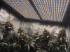
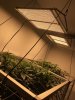
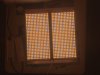
But for now, these are my plants (Mental Floss by Chimera - lovely smoke, BTW):
I thought I'd better post a thread explaining what "High Lights" are and how (and why) they're different to most other boards on the market. These boards are designed and assembled in Australia and use Japanese-made Nichia and Korean Seoul Semiconductor UV white phosphor 3030 LEDs.
The boards were designed by growers for growers and are purely flowering boards - although we have been using them in veg and, apart from a bit of extra stretch, they have been performing well.
Basically they are a 4.5A @ 50.5V board that can be driven as high as 225W+ with matching heatsinks, but do not require heatsinks at 3A or below (around 150W). This is due to the large platform and LED spacing.
The boards measure 415mm x 205mm x 2mm (aluminium) and have 450 LEDs. When paired together, they form a perfect square of 415mm x 410mm, or 16" x 16" in the old money, with a combined 900 LEDs.
The LED arrangement in this configuration is 30 x 30 LEDs, and they come in two colours: one board has two types of high CRI LEDs (90 + 98 ) with added UVA 6500K white phosphor LEDs (CRI95) for a total 2950K, while the other features the two high CRI LEDs without UV for a nominal 2700K.
Both boards have a combined CRI95 - arguably one of the highest CRIs on the market - using the highest efficiency and top flux bins of their type. I'll provide more details on the actual LEDs in the next post.
One advantage of these boards is they can be run on most 48V-54V drivers commonly used in strip and HLG type builds, and do not require a second channel (driver) for the UV component. They also have a dedicated heatsink option, but can also be mounted on HLG type heatsinks.
Paired in a square configuration, they are designed as a true 600W HPS killer running at up to 400W (per pair) and covering a 3'x3' area.
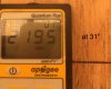
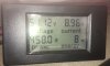
They can also be paired to cover a 2'x2' grow area without heatsinks running at half that wattage. The boards in the first photo above are running at about 95W each for a combined 190W, or 210W at the wall.
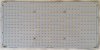
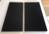
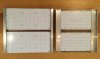
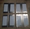
Here is a photo of a two-colour board showing the layout. The black lines and circles denote "safe" areas that can be drilled out if need be. For example, if not using heatsinks, the middle 4mm mounting holes can be drilled out to provide a bit of air circulation, whilst the 4mm corner holes can be drilled out to 6mm to accommodate hangar hooks etc. Ostensibly the "safe" areas are designed as a guide for mounting screws, washers (optional, but not really required) and hanging hardware. The Molex wire connectors are rated up to 9A, which means you can safely wire two boards in parallel and run them at their maximum rating. More boards can be wired in parallel using Wagos or terminal blocks etc, and of course they can also be run in series.
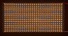
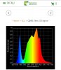
Here is a three-colour board. There are really only two "colours" - 2700K and 6500K - but there are three different types of LED (CRI 90@2700K, CRI98@2700K, CRI95@6500K), which is not at first obvious.
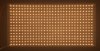
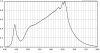
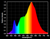
Here is a two-colour board. The two-colour boards are design for those who are already running supplemental UV and require lots of red, or those who might want to use them to supplement their existing veg boards/strips (3500K-5000K etc) for flowering. They have an excellent red:far red ratio and plenty of 620-660nm spectra, as you will soon see.
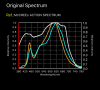
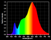
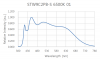
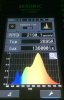
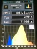
The spectra of each board is perhaps the most interesting thing about them, and I will go into further detail in the next post.
There were a number of reasons for designing and building these boards, so I will explain their philosophy.
Firstly, a lot of commercial growers have open rooms with stations that typically measure 3'x3' - which is the ideal footprint for a 600w HPS. Furthermore, many growers looking to switch from HPS to LED are already using 600W HPS lamps - the industry standard - but there are no real LED boards designed to truly replace a 600W HPS. Most LED boards are designed to fit in tents ranging in size from 2.5x2, to 4x2, to 4x4 etc.
We wanted to design a board that would truly be a 600W HPS killer, replacing it with better quality light, a much more even footprint, and enough power to produce the same yields with 2/3 the electricity.
There are plenty of strips and boards on the market that can be used for veg or dual-purpose veg and flowering, but there are not as many that serve as pure flowering boards, which again is the aim of replacing a 600 HPS.
So that was the first aim. And the first problem: a single board would be much too big to replace a 600W HPS, so we designed the ideal footprint and then cut it in half to produce a board that could be mounted in pairs (16"x16" square configuration), or in other configurations depending on grow area. The boards are 1.5 times the size of HLG's QB boards, so can also be used in tents (one board per 2'x2').
The next aim was to produce a board that could be run soft without a heatsink, or run hard with a heatsink - giving the grower the option to run them anywhere from 75W to 225W per board, depending on their budget and grow style.
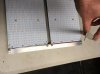
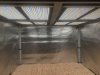
To do this, dedicated heatsinks were required, and these were modelled on HLG Slate 2 clones. Mainly because they were a cheap existing design, but also because those with HLG type heatsinks could use them with these boards.
We trialled two heatsinks and went with the heatsink on the left, as it was a little bit lighter and testing showed it was more than adequate to cool the boards. Incidentally, the heatsinks measure 444mm x 206mm and so are equal to one half of a HLG Slate 2 triple heatsink (891mm x 205mm) - cut one in half, and you have two High Light heatsinks. The High Light heatsinks are, however, a slightly heavier design at 1.2kg each (compared with 1kg for a similar sized Slate 2 design). They are obviously pre-drilled for the boards and have 5mm (3/16") mounting holes on each corner.
If you are going to spend money on LEDs, then you may want the option to drive them hard, right?
Well, our philosophy was there are always new LEDs around the corner, so if you're a commercial grower, you can afford to run these hard for a couple of seasons and then replace them if you so wish. Or just keep running them. They are a true 225W board, so you can get the most out of them if required. Just bear in mind they won't be as efficient at 225W as they will be at 95W . . .
Flexibility, as you can see, was the third requirement. The ability to use existing drivers was factored in. These boards will drop about 48V at half power, rising to about 50-50.5V at full power. Most 48V "A" type HLG drivers will supply the 50.5V required at full power, while 48V "B" type drivers can supply half current. If you want to drive the boards at full current with a "B" type driver, then 54V will fit the bill.
Finally, the boards needed to be a robust design with good light spread and heat dissipation: and that is why 2mm aluminium PCBs were chosen with an even spread of LEDs to produce the most even footprint and heat markers.
By now, you're probably wondering about the spectra and choice of LEDs . . .
But for now, these are my plants (Mental Floss by Chimera - lovely smoke, BTW):
I thought I'd better post a thread explaining what "High Lights" are and how (and why) they're different to most other boards on the market. These boards are designed and assembled in Australia and use Japanese-made Nichia and Korean Seoul Semiconductor UV white phosphor 3030 LEDs.
The boards were designed by growers for growers and are purely flowering boards - although we have been using them in veg and, apart from a bit of extra stretch, they have been performing well.
Basically they are a 4.5A @ 50.5V board that can be driven as high as 225W+ with matching heatsinks, but do not require heatsinks at 3A or below (around 150W). This is due to the large platform and LED spacing.
The boards measure 415mm x 205mm x 2mm (aluminium) and have 450 LEDs. When paired together, they form a perfect square of 415mm x 410mm, or 16" x 16" in the old money, with a combined 900 LEDs.
The LED arrangement in this configuration is 30 x 30 LEDs, and they come in two colours: one board has two types of high CRI LEDs (90 + 98 ) with added UVA 6500K white phosphor LEDs (CRI95) for a total 2950K, while the other features the two high CRI LEDs without UV for a nominal 2700K.
Both boards have a combined CRI95 - arguably one of the highest CRIs on the market - using the highest efficiency and top flux bins of their type. I'll provide more details on the actual LEDs in the next post.
One advantage of these boards is they can be run on most 48V-54V drivers commonly used in strip and HLG type builds, and do not require a second channel (driver) for the UV component. They also have a dedicated heatsink option, but can also be mounted on HLG type heatsinks.
Paired in a square configuration, they are designed as a true 600W HPS killer running at up to 400W (per pair) and covering a 3'x3' area.
They can also be paired to cover a 2'x2' grow area without heatsinks running at half that wattage. The boards in the first photo above are running at about 95W each for a combined 190W, or 210W at the wall.
Here is a photo of a two-colour board showing the layout. The black lines and circles denote "safe" areas that can be drilled out if need be. For example, if not using heatsinks, the middle 4mm mounting holes can be drilled out to provide a bit of air circulation, whilst the 4mm corner holes can be drilled out to 6mm to accommodate hangar hooks etc. Ostensibly the "safe" areas are designed as a guide for mounting screws, washers (optional, but not really required) and hanging hardware. The Molex wire connectors are rated up to 9A, which means you can safely wire two boards in parallel and run them at their maximum rating. More boards can be wired in parallel using Wagos or terminal blocks etc, and of course they can also be run in series.
Here is a three-colour board. There are really only two "colours" - 2700K and 6500K - but there are three different types of LED (CRI 90@2700K, CRI98@2700K, CRI95@6500K), which is not at first obvious.
Here is a two-colour board. The two-colour boards are design for those who are already running supplemental UV and require lots of red, or those who might want to use them to supplement their existing veg boards/strips (3500K-5000K etc) for flowering. They have an excellent red:far red ratio and plenty of 620-660nm spectra, as you will soon see.
The spectra of each board is perhaps the most interesting thing about them, and I will go into further detail in the next post.
There were a number of reasons for designing and building these boards, so I will explain their philosophy.
Firstly, a lot of commercial growers have open rooms with stations that typically measure 3'x3' - which is the ideal footprint for a 600w HPS. Furthermore, many growers looking to switch from HPS to LED are already using 600W HPS lamps - the industry standard - but there are no real LED boards designed to truly replace a 600W HPS. Most LED boards are designed to fit in tents ranging in size from 2.5x2, to 4x2, to 4x4 etc.
We wanted to design a board that would truly be a 600W HPS killer, replacing it with better quality light, a much more even footprint, and enough power to produce the same yields with 2/3 the electricity.
There are plenty of strips and boards on the market that can be used for veg or dual-purpose veg and flowering, but there are not as many that serve as pure flowering boards, which again is the aim of replacing a 600 HPS.
So that was the first aim. And the first problem: a single board would be much too big to replace a 600W HPS, so we designed the ideal footprint and then cut it in half to produce a board that could be mounted in pairs (16"x16" square configuration), or in other configurations depending on grow area. The boards are 1.5 times the size of HLG's QB boards, so can also be used in tents (one board per 2'x2').
The next aim was to produce a board that could be run soft without a heatsink, or run hard with a heatsink - giving the grower the option to run them anywhere from 75W to 225W per board, depending on their budget and grow style.
To do this, dedicated heatsinks were required, and these were modelled on HLG Slate 2 clones. Mainly because they were a cheap existing design, but also because those with HLG type heatsinks could use them with these boards.
We trialled two heatsinks and went with the heatsink on the left, as it was a little bit lighter and testing showed it was more than adequate to cool the boards. Incidentally, the heatsinks measure 444mm x 206mm and so are equal to one half of a HLG Slate 2 triple heatsink (891mm x 205mm) - cut one in half, and you have two High Light heatsinks. The High Light heatsinks are, however, a slightly heavier design at 1.2kg each (compared with 1kg for a similar sized Slate 2 design). They are obviously pre-drilled for the boards and have 5mm (3/16") mounting holes on each corner.
If you are going to spend money on LEDs, then you may want the option to drive them hard, right?
Well, our philosophy was there are always new LEDs around the corner, so if you're a commercial grower, you can afford to run these hard for a couple of seasons and then replace them if you so wish. Or just keep running them. They are a true 225W board, so you can get the most out of them if required. Just bear in mind they won't be as efficient at 225W as they will be at 95W . . .
Flexibility, as you can see, was the third requirement. The ability to use existing drivers was factored in. These boards will drop about 48V at half power, rising to about 50-50.5V at full power. Most 48V "A" type HLG drivers will supply the 50.5V required at full power, while 48V "B" type drivers can supply half current. If you want to drive the boards at full current with a "B" type driver, then 54V will fit the bill.
Finally, the boards needed to be a robust design with good light spread and heat dissipation: and that is why 2mm aluminium PCBs were chosen with an even spread of LEDs to produce the most even footprint and heat markers.
By now, you're probably wondering about the spectra and choice of LEDs . . .


 None! ...at least till now, lol!