You are using an out of date browser. It may not display this or other websites correctly.
You should upgrade or use an alternative browser.
You should upgrade or use an alternative browser.
Help!!! ( electrical) how do i.. (diagrams+pics needed!!!)
- Thread starter stelthy
- Start date
whiteflour
Well-Known Member
Yes a light stranded wire to the wall then I would use some heavier solid wire in between the sockets (not necessary but it makes things more secure).
whiteflour
Well-Known Member
Switches are wired inline on the hot leg.
stelthy
Well-Known Member
Yes a light stranded wire to the wall then I would use some heavier solid wire in between the sockets (not necessary but it makes things more secure).
Ok cool
stelthy
Well-Known Member
Switches are wired inline on the hot leg.
??? What does that mean? lol - STELTHY
whiteflour
Well-Known Member
You'll just take a length of lamp cord then slice through one of the wires (your hot leg) and put the switch in between the splice. That sliding light switch might actually bite into the wire and make the connection for you.
stelthy
Well-Known Member
You'll just take a length of lamp cord then slice through one of the wires (your hot leg) and put the switch in between the splice. That sliding light switch might actually bite into the wire and make the connection for you.
So the switch is kinda like this ? -------------------/ switch /-------------------- and on the live (brown) wire? - STELTHY
whiteflour
Well-Known Member
Yep you've got the idea.
stelthy
Well-Known Member
Yep you've got the idea.
Excellent mate, cheers for the help I'll add more REP to you as soon as I am allowed
whiteflour
Well-Known Member
No problem. Let me know how it works out.

chainseeker
Well-Known Member
Hey stealthy How many wires r coming out of the sockets that ur screwing ur lights into. If they have three then why not use the ground? If they only have two I would def. wire up like the first diagram that whiteflour drew 4 ya. It dont really matter as long as u keep all the hots tied together all the grounds tied together and all the neutrals tied together! It's that simple!
sonar
Well-Known Member
Hey man I saw this post and it seems like whiteflour has ya straightened out. I'm an electrician (USA) and everything he said was on the mark, at least for the USA. I know you guys in Europe do things a little bit different, but in theory it's pretty much the same. You guys run on 240V and 50Hz, right?
Just remember, a switch must always go on the hot leg like he said. In the US, that would generally be the black wire, but it looks like you guys have a different color code.
+rep whiteflour
Just remember, a switch must always go on the hot leg like he said. In the US, that would generally be the black wire, but it looks like you guys have a different color code.
+rep whiteflour
chainseeker
Well-Known Member
Yeah the only thing I would add is if it is 240 I would def. run all wires into an electrical box and make your connections inside the box. Def. don't tape the wires use connectors.
stelthy
Well-Known Member
Lol ok I thought I knew what I was doing but now I am confused again... In the US people only wire things with 2-core? but here in the UK am I correct in saying I should be using 3-core throughout ? I'll take some pics of the inside (connections) etc of the switch and the bulb holders etc.. As I really want to get this step done today please reply with help, pics and or diagrams for UK wiring of my stuff in the above pics HELP = GOOD REP! cheers - STELTHY
stelthy
Well-Known Member
Yeah the only thing I would add is if it is 240 I would def. run all wires into an electrical box and make your connections inside the box. Def. don't tape the wires use connectors.
Do I need to buy an electrical box? is that like a junction box? oh PS/ don't worry about the elec. tape I only got it really 'cos I ran out and needed some for my toolbox
chainseeker
Well-Known Member
I use three core for everything I can esp. when it comes to safety in my own house I'll try to draw up a 3 core wire setup 4 ya
stelthy
Well-Known Member
I use three core for everything I can esp. when it comes to safety in my own house I'll try to draw up a 3 core wire setup 4 ya
Ok cheers man that would be well helpful
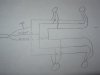
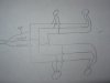
chainseeker
Well-Known Member
Ok 4give my lack of art's and photography hope these help. Basically if all the hots make contact all the neutrals make contact and all the grounds make contact u r good to go. I would run all the wires into the box and then u can just match up the colors from the sockets in the box. Then series ur switch into the hot now bring ur power in the box and hook ground to ground hot to hot and neutral to neutral. Good luck to ya ur getting close.
Attachments

Similar threads
- Replies
- 15
- Views
- 1K
- Replies
- 9
- Views
- 822