You are using an out of date browser. It may not display this or other websites correctly.
You should upgrade or use an alternative browser.
You should upgrade or use an alternative browser.
A Bored Electrician to Answer Your Questions
- Thread starter IAm5toned
- Start date
you should be fine, you could use the pc power supply forever. the train controller was for someone that wanted to be able to control the speed of the fans...
Thanks dude....I realised later that i had a 12v dc drill charger that was not being used so I cut the end of and wired up my inlet and exhausts with it( both being 12v dc fans)
They went flat out and LOUD which really meant for a lack of stealth, not including the air movement was overkill for a little cabinet...so I found an old phone charger(5.2v dc) and retried with this....dropped the speed somewhat, but dropped the noise remarkably...just thought Id wack that in here just in case someone else was thinking the same as me...might save them a trip to the Sunday markets...the crowds...the germs...the screaming children...the people that walk too slow or the wrong direction....!!!!
Troy
IAm5toned
Well-Known Member
Thanks dude....I realised later that i had a 12v dc drill charger that was not being used so I cut the end of and wired up my inlet and exhausts with it( both being 12v dc fans)
They went flat out and LOUD which really meant for a lack of stealth, not including the air movement was overkill for a little cabinet...so I found an old phone charger(5.2v dc) and retried with this....dropped the speed somewhat, but dropped the noise remarkably...just thought Id wack that in here just in case someone else was thinking the same as me...might save them a trip to the Sunday markets...the crowds...the germs...the screaming children...the people that walk too slow or the wrong direction....!!!!
Troy
thats a pretty clever fix...
...id keep an eye on that charger tho... its prolly gonna want to get hot. +rep for creativity tho lol
cheers man, I actually did think of heat when I first setup the power points and I actually have the inlet pulling air past all of them, nothing is getting hot, which is always a nice thing...when the box is made of wood...and its where ya sleep!!
Btw...now that i have the fans and the new light in operation...the babies are loving it!!!!!! seen massive differences in the last week
Troy
Btw...now that i have the fans and the new light in operation...the babies are loving it!!!!!! seen massive differences in the last week
Troy
IAm5toned
Well-Known Member
yes and yes!Hey just a quick question, I've got a limited amount of plug sockets so I put two CFLs in parallel through the same plug, they should work as normal right? Also does Watts=Volts x Amps?
always connect in parallel

marcraiderfan
Active Member
I am running two 1000w HID's and a vortex exhaust..also a couple of regular house fans in the room. I am running a heavy duty extension cord with three femal inputs at the end.
1)I wanted to know if I can connect the two ballasts and the vortex exhaust fan to one cord or if I should run two extension cords?
2)If I need to run two seperte cords can they come from the same 110 outlet?
3) The timers I was going to use are 1000w max, do they make larger capacity ones?
Thanks for the help
IAm5toned
Well-Known Member
ok check it out-I am running two 1000w HID's and a vortex exhaust..also a couple of regular house fans in the room. I am running a heavy duty extension cord with three femal inputs at the end.
1)I wanted to know if I can connect the two ballasts and the vortex exhaust fan to one cord or if I should run two extension cords?
2)If I need to run two seperte cords can they come from the same 110 outlet?
3) The timers I was going to use are 1000w max, do they make larger capacity ones?
Thanks for the help
Absolutely1)I wanted to know if I can connect the two ballasts and the vortex exhaust fan to one cord or if I should run two extension cords?
not, unless you have BOTH of the following:
a #10awg extension cord.
e dedicated 20amp circuit feeding a Spec Grade 20amp Rated receptacle
seriously, dont try to run that much off a cord unless you have designed it just for that purpose
Again, too much power for anything but a dedicated 20amp spec grade receptacle... when your reaching the point of 2000w or greater total load, you really need to have dedicated circuits. however if you must, find a seperate outlet on a different circuit for the second cord.2)If I need to run two seperte cords can they come from the same 110 outlet?
they do, however after about 20 amps/2500w it can be cheaper to use a relay circuit (controlled by a cheap timer) to switch a general purpose contactor.(remote controlled switch) tork and intermatic manufactur some heavy duty electromechanical timeclocks however they get pretty pricey.3) The timers I was going to use are 1000w max, do they make larger capacity ones?
marcraiderfan
Active Member
ok check it out-
Absolutely
not, unless you have BOTH of the following:
a #10awg extension cord.
e dedicated 20amp circuit feeding a Spec Grade 20amp Rated receptacle
seriously, dont try to run that much off a cord unless you have designed it just for that purpose
Again, too much power for anything but a dedicated 20amp spec grade receptacle... when your reaching the point of 2000w or greater total load, you really need to have dedicated circuits. however if you must, find a seperate outlet on a different circuit for the second cord.
they do, however after about 20 amps/2500w it can be cheaper to use a relay circuit (controlled by a cheap timer) to switch a general purpose contactor.(remote controlled switch) tork and intermatic manufactur some heavy duty electromechanical timeclocks however they get pretty pricey.
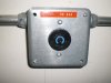
Thanks for the advice. I do have a 240 outlet that is about 40 ft away I could use. Can I run an extension cord and a power strip to this to run both lights?
Here is a picture of the outlet
Attachments
marcraiderfan
Active Member
Thanks for the advice. I do have a 240 outlet that is about 40 ft away I could use. Can I run an extension cord and a power strip to this to run both lights?
Here is a picture of the outlet
Ok the guy that lived here before was a retired electician and wired some circuits in the garage. I have an outlet that looks like it is split between two circuits..check these pics out and let me know what you think..I also put a picture of the extension cord specs- I have two of the extension cords so I could run one to each light
Attachments


marcraiderfan
Active Member
Ok the guy that lived here before was a retired electician and wired some circuits in the garage. I have an outlet that looks like it is split between two circuits..check these pics out and let me know what you think..I also put a picture of the extension cord specs- I have two of the extension cords so I could run one to each light
OK before you take the time to answer anymore questions... I am going to have an electrician buddy of mine come out and wire a 220 set up for me... I figure I am already almost 3 grand into this set up, I am not going to cut corners now...Thanks for the advice though..it was the shove I needed to pay a professional to do my wiring... if I knew how to give you rep I would, but I am a total newbe to this forum
IAm5toned
Well-Known Member
lol its all good man... from the pic i would say your good to go using that split receptacle for temporary service though untill your pro gets done..OK before you take the time to answer anymore questions... I am going to have an electrician buddy of mine come out and wire a 220 set up for me... I figure I am already almost 3 grand into this set up, I am not going to cut corners now...Thanks for the advice though..it was the shove I needed to pay a professional to do my wiring... if I knew how to give you rep I would, but I am a total newbe to this forum

hwy420
Well-Known Member
Hey bro, I just want to say thanks for helping in my endeavors thus far; you have really been a blessing to me during my quest to build in my grow room. I would like to ask help on how to wire my power outlet. As you may recall, on my last post for advice, I had accidentily cut into a peice of existing romex that fed power to my 'bonus room' outlets. This time, I intentionally cut into a different line supplying power to 'bedroom 3' for the purpose of adding an outlet/receptacle to my grow room. I bought the blue plastic (nonmetallic) box at lowes, and a 15amp 125V outlet, and i'm ready to wire it so the new outlet will work, and the existing outlet(s) in 'bedroom 3' will still work.
Which silver screw do I connect the white incoming electrical wire? The top silver screw or bottom one?
Which brass screw do I attach the black incoming electrical wire? The top brass screw or bottom one?
Which silver screw do I attach the white outgoing electrical wire? The top silver screw or bottom one?
Which brass screw do I attach the black outgoing electrical wire? The top brass screw or bottom one?
How do I wire my ground wires? Attach them both to the ground screw (green screw)?
Attachments
-
 hwy420-albums-attic-storage-room-project-picture84746-incoming-ground-wire-connection.jpg34.7 KB · Views: 7
 -
 hwy420-albums-attic-storage-room-project-picture84747-incoming-hot-wire-black-connection.jpg23.3 KB · Views: 6
 -
 hwy420-albums-attic-storage-room-project-picture84748-incoming-white-wire-connection.jpg28.2 KB · Views: 8
IAm5toned
Well-Known Member
haha i found someone elses image to steal to show you howHey bro, I just want to say thanks for helping in my endeavors thus far; you have really been a blessing to me during my quest to build in my grow room. I would like to ask help on how to wire my power outlet. As you may recall, on my last post for advice, I had accidentily cut into a peice of existing romex that fed power to my 'bonus room' outlets. This time, I intentionally cut into a different line supplying power to 'bedroom 3' for the purpose of adding an outlet/receptacle to my grow room. I bought the blue plastic (nonmetallic) box at lowes, and a 15amp 125V outlet, and i'm ready to wire it so the new outlet will work, and the existing outlet(s) in 'bedroom 3' will still work.
Which silver screw do I connect the white incoming electrical wire? The top silver screw or bottom one?
Which brass screw do I attach the black incoming electrical wire? The top brass screw or bottom one?
Which silver screw do I attach the white outgoing electrical wire? The top silver screw or bottom one?
Which brass screw do I attach the black outgoing electrical wire? The top brass screw or bottom one?
How do I wire my ground wires? Attach them both to the ground screw (green screw)?

you can see how you use a few wirenuts to make jumpers going to the plug when your dealing with more than one romex cable in the outlet box... this particular picture he's using two plugs but it will work where there is just one.
however for the record it does not matter which screw the wire hits as long as the right wire is going to the right color screw... theres two screws for each of the conductors and one screw for gnd... so one white would go under each silver screw, one black under each brass screw. youll have to make a jumper for the ground cuz two wires wont fit under one screw, and if you make two wires fit under one screw they wont stay there long, slips off eveytime. since your going to be running some lights on this wire i would do it like its shown in the image
BloodShot420
Well-Known Member
yo Iam5toned! i got another question for you...
i'm setting up my PLC... i need to get 3-4 pairs of wires to carry a 24v DC signal to turn on some devices in another room... i've been looking for some cheap cable with mulitple conductors (for lawn sprinkler systems and shit) but i'm wondering - will standard cat5 cables work if i used the 4 twisted pairs to run 4 24v dc signals to turn on some solid state relays? (one of which turns on an industrial motor starter which the ballasts are run from)..
the cable is cat 5e - 4 pairs of 24gauge solid core wire... what do you think?
IAm5toned
Well-Known Member
you took the words right out of my mouth..lol as long as your using ONLY solid state relays the cat 5 should work just fine, as the solid state relay uses a tiny amount of current to activate an led which in turn causes the relay to turn on...yo Iam5toned! i got another question for you...
i'm setting up my PLC... i need to get 3-4 pairs of wires to carry a 24v DC signal to turn on some devices in another room... i've been looking for some cheap cable with mulitple conductors (for lawn sprinkler systems and shit) but i'm wondering - will standard cat5 cables work if i used the 4 twisted pairs to run 4 24v dc signals to turn on some solid state relays? (one of which turns on an industrial motor starter which the ballasts are run from)..
the cable is cat 5e - 4 pairs of 24gauge solid core wire... what do you think?
just be very careful when stripping the outer jacket of the cat5, its very very easy to put a nick in the insulation on one of the pairs, and with 24v on it... bad news.
there are actually automation systems that use patch cables just for this application
and there was study done by some college kids that actually built a solid state device from scratch and wrote software for a simple system to control xmas lighting using the paralell port on a desktop pc based on this same principal... a good google search will dig up the project guideline and schematics
jats
Well-Known Member
OK before you take the time to answer anymore questions... I am going to have an electrician buddy of mine come out and wire a 220 set up for me... I figure I am already almost 3 grand into this set up, I am not going to cut corners now...Thanks for the advice though..it was the shove I needed to pay a professional to do my wiring... if I knew how to give you rep I would, but I am a total newbe to this forum
you give rep by clicking on the set of scales in the top right hand corner of the post you want to rep....and it'll take it from there
BloodShot420
Well-Known Member
you took the words right out of my mouth..lol as long as your using ONLY solid state relays the cat 5 should work just fine, as the solid state relay uses a tiny amount of current to activate an led which in turn causes the relay to turn on...
just be very careful when stripping the outer jacket of the cat5, its very very easy to put a nick in the insulation on one of the pairs, and with 24v on it... bad news.
there are actually automation systems that use patch cables just for this application
and there was study done by some college kids that actually built a solid state device from scratch and wrote software for a simple system to control xmas lighting using the paralell port on a desktop pc based on this same principal... a good google search will dig up the project guideline and schematics
Perfect - thank you for the info... exactly what i wanted to hear....
i can now hook up extra grows to a plc with an ethernet cable!
what do you think would happen if i used one of the twisted pair for a 0-10v (or 4-20ma) signal back from a sensor in grow#2... probably about 50ft away from the plc.. would all the other 24v wires mess with it (the signal), if they were turning on and off every so often?
thanks again for the info!!
IAm5toned
Well-Known Member
Perfect - thank you for the info... exactly what i wanted to hear....
i can now hook up extra grows to a plc with an ethernet cable!I love it...
what do you think would happen if i used one of the twisted pair for a 0-10v (or 4-20ma) signal back from a sensor in grow#2... probably about 50ft away from the plc.. would all the other 24v wires mess with it (the signal), if they were turning on and off every so often?
thanks again for the info!!
well what is the nature of the signal? is it simple dry contact circuit? or is it a voltage trigger?
Similar threads
- Replies
- 101
- Views
- 8K
- Replies
- 51
- Views
- 4K
- Replies
- 10
- Views
- 3K