LED DIY : Making of a "DJ SET "-style grow led light .

stardustsailor

Well-Known Member
Thats clean. disguised as a camping stove. Nice....
Just wait ..
Ya'll see what that "camping stove" will be able to .."cook " ....
It will make all other types of grow lights (all of them ... ) ,look like dinner candle lights ...

Coming soon ....
Then we 'll see who's going to take a hike .....for camping ....
This baby ?
Or all the rest ?


(Trust me ...I know perfectly well , what I'm talkin' about ....)
 

stardustsailor

Well-Known Member
Some more details ....
P2155961.JPGP2155962.JPGP2155965.JPG
...........
And the hole that lid came with ....
Became a 'driver pcb' attachment ....
(small driver pcb will be attached via small screw to black plastic holder ...)
P2155964.JPGP2155959.JPG
 

stardustsailor

Well-Known Member
Guod ..
A question ...

I got 180 Ω 1206 SMD resistors (Vishay)

http://www.mouser.com/ds/2/427/dcrcw-72725.pdf

And a 1 K pot (Vishay-Spectrol )

http://www.mouser.com/ds/2/427/536-89442.pdf

Now ...This pot is a precision potentiometer with 10 turns from one end to other ...

( 0.2459 Ω/turn )

Since analog dimming is linear to pot ...
And "one end" is at 120mA..
The other is at 700mA ...
580mA difference ....
That means ~58mA increase/decrease per turn of pot ?

So it will be like :
Position '0' =>700mA
half turn => 671 mA ( ....700 - {58/2} ) .....~ 670 mA
1 turn => 642 mA .....~ 640mA
2 turns => ~ 580mA
3 turns => ~520mA
4 turns => ~ 480mA
5 turns => ~ 420mA
6 turns => ~ 340mA .....(in fact is 352 mA ....)

Right ?
 

guod

Well-Known Member
right, but i think it´s to fine for this
check the relative Radiant power chart for the oslons and you will see what i mean.
 

stardustsailor

Well-Known Member

guod

Well-Known Member
What matters is that this is a really compact ,tough and highly efficient design ...
yes, I always try to get close to the "KISS principle" keep it smart and simple, or straightforward, stupid...

from Wikipedia...
The principle most likely finds its origins in similar concepts, such as Occam's razor, Leonardo da Vinci's "Simplicity is the ultimate sophistication", Mies Van Der Rohe's "Less is more", or Antoine de Saint Exupéry's "It seems that perfection is reached not when there is nothing left to add, but when there is nothing left to take away"

a other rule of mine is...
Form follows function


stardustsailor

Well-Known Member
"It seems that perfection is reached not when there is nothing left to add, but when there is nothing left to take away"

Well ...Little Prince's author is right ....
...
But I wanna make it look "audiophile " again ....
;-P ...
P2155969.JPG
Oh ,Guod I wish I had just 1% of your knowledge about electronics ...
P2155971.JPGP2155972.JPG...
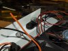
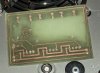
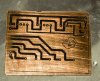
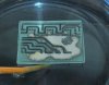
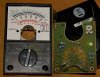
Old cheapo multimeter with analog indication pin ..
No need for external power supply to measure El. Current ...
(*Analog =>magnet + coil operation...Works with the current that measures ...
Sometimes/often , analog stuff are just great !!! )
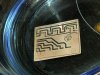
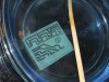
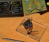
All it's needed to work from 120mA to 700mA is probably the right resistor ....
And I do not have the slightest idea which that might be ....

And then ,to be connected in series with one of the drivers .....
(...It will measure just one driver ,but since it going to be the "master " ...)


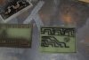
Further than looks ,it could be handy ,to watch real-time the drivers output current ....
(without complex additional electronics or 5 Volt PSUs/regulators ...)
...
Anyway ...
Just a thought ....
 

stardustsailor

Well-Known Member
And one thing more ....

Say ,that the box is working with the fan(s) on ,but without any leds switched on...

Say T ambient is (what else ? ) 25°C ......

If after a while of operation ,heatsink temp stabilises at about i.e 5 °C lower (!!!) than T ambient ....
Althought that would depend on other factors like space/air volume ....
Since camping 12V small plastic portable fridges use just a fan and a heatsink to freeze goods ..
No "phase change" there ....(like with normal household freezers ..)
And after couple of days ,if they will remain unopened ,ice forms !!!....
So the box-without the leds - actually could be a ..camping freezer ....Rather than .."stove" ...
If placed in a small ,thermally isolated ,box ......
Then ,calculating heat power (in Watts ) from leds (through "efficiency " figures ..) ....

And then operate the box with both leds and fan(s) switched on .....
If heatsink temp is 2°C above ambient ....

Will it be right to speculate :

25° + 2° C = (25-5 ) + ( Total Thermal Resistance heat path x Watts of heat )*


*( in example case ( Total Thermal Resistance heat path x Watts of heat )= 7°C
If led efficiency is ~.45 then : A box at full power -700mA, ~ 70Watts - will emit 38.5 Watts of heat .....

Total Thermal Resistance heat path of box then would have been 7 / 38.5 = 0.18 C/W (just random numbers there ...)

Is that way of "calculating / estimating " total thermal resistance ,wrong ?

Because if correct and not wrong , then at that case (of example ) Tj is just 34°C !!! **


**Rθ total= { Δ ( Tj -Theatsink )} / P heat =>
Tj =( Rθ total x P heat ) + T heatsink ....

???
 

stardustsailor

Well-Known Member
...
-Found perfect paper for thermal transferring ....
Lidl Market flyers.. Just Smooooooothhhh transferring !!!!
Amazing !

-Cheapo of the cheapos , FR4 pcb used ( 100 x 100 mm =0.5 € ! )

-Drills ( .6 - 1 mm ) play games on me ...
Or my eyes ...
Too much vibration on drill tip ...
Drill is straight ,though ...
WTF ?
(even on lowest rpm setting .... )

...
Anyway ....
Later ....
After paying a visit on a local bar ....
I'll try #2 ....
;-P


P2155974.JPG
 

guod

Well-Known Member
Nice pcb but is wrongly printed ..Forgot to "mirror" the image ..

every newbie has to go this way... best way to learn it...;-)

for your drilling problem goggle "pcb drills and routers" and take a look on goggle pics or clamped the drill very short.
go for a drillspeed above 6000U/min @ 0.6mm
 
Top