I NEED HELP 5V TO 10V PWM

Growmau5

Well-Known Member
Hey guys, I have been looking through @stardustsailor 's old threads trying to find the answer and avoid making this post. But I am having a little trouble deciphering the lingo.

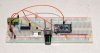
THE GOAL: use a 0-5v pwm signal from a controller like an arduino to control an led driver like an HLG with a 0-10v dimming lead.

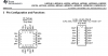
OPTION 1: use a OP amp like a Texas Instruments LM324 to boost the 5v signal to a 10v signal via a separate 12v dc power source adjusted down to 10v.
arduino 10 analog diagram.png
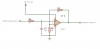
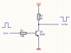
OPTION 2: use a mosfet or transistor like LM317T to do something?
10v pwm from arduino.png

if you can help me, please respond as though you are talking to someone with next to no circuit building experience. Thank you!
 

Growmau5

Well-Known Member
Option 2 is more practical. You shouldn't need an op amp circuit. Btw, that op amp circuit is a low pass filter, so it will smooth out the signal. (that'd work either way, giving an output from 0-10V rather than PWM)
thanks church, Radioshack had all the parts for option 1, so that is what I have available anyways. the op amp was only $1.49 so if it smooths out the signal a little bit, thats cool with me.
This thing has two rows of 7 pins on it, so I dont really understand how to wire it. I assume most of the pins go un-used, im sure there are some additional instructions out there.
 

churchhaze

Well-Known Member
thanks church, Radioshack had all the parts for option 1, so that is what I have available anyways. the op amp was only $1.49 so if it smooths out the signal a little bit, thats cool with me.
This thing has two rows of 7 pins on it, so I dont really understand how to wire it. I assume most of the pins go un-used, im sure there are some additional instructions out there.
It's the RC circuit feeding into the non-inverting input that smooths it out. If you take that out, it should just act as an amplifier with a gain of 2x. It shouldn't matter whether you leave it in or take it out since the DIM input smooths out PWM input anyway. That's how it can accept either PWM or 0-10V input.
 

mc130p

Well-Known Member
thanks church, Radioshack had all the parts for option 1, so that is what I have available anyways. the op amp was only $1.49 so if it smooths out the signal a little bit, thats cool with me.
This thing has two rows of 7 pins on it, so I dont really understand how to wire it. I assume most of the pins go un-used, im sure there are some additional instructions out there.
upload_2015-12-29_22-52-8.png
upload_2015-12-29_22-53-2.png
There are 4 op-amps per chip, so you won't need most of the pins. Looks like you need 1-4, 11.
 
Last edited:

salmonetin

Well-Known Member
....i saw other way ...via a separate 12v dc power source.... ...7810 and ICL7667...a double mosfet...for meanwell "d" ... i dont know if work ok for other models...or its ok for you... maybe other bro can said more...


...from...

http://www.todomarino.com/forum/showthread.php?75477-Conversor-0-5v-PWM-a-0-10v

...other idea or example...
...i know Wilson...maybe only ok for advanced diyers...;)...:fire:


0-10V Analog to 5V PWM convertor using the ever popular ATMEGA 328-AU Microcontroller. This was accomplished by passing the 0-10V Analog through a voltage divider circuit which cuts the signal down to a 0-5V signal that’s compatible with the Atmega’s analog inputs. Each input converts the 0-5V ANALOG signal into a number between 0-1023 (0V=0, 5V=1023) The resulting signal value is then converted into a 5V PWM 8 bit signal, whose value can range from 0 - 255. (0V=0%PWM, 1023=255 or 100% PWM ) The PWM signal is then output to the led driver’s PWM input.
The software used to do the Analog/Digital conversion includes an “Averaging “ function, to smooth the output signal, in an attempt to reduce spurious or induced electrical “noise” from causing “flickering” in the LED’s

http://www.plantedtank.net/forums/20-diy/519649-diy-knob-dimmer-pwm-based-led-drivers.html

pd... i noticed you have a "curious" typhon controller... same of positivity... ..maybe you must download and read or look... the Typhon v3.pdf ....inside typhon 2.1 ....;)

https://github.com/SaltyDog-Aquariums/Typhon-v2.1

..links..and pics are only for examples or ideas...

:peace:

Saludos
 
Last edited:

wietefras

Well-Known Member
I made a 0-10V PWM using a stepper motor driver that I had laying around:
20140929_FanControllerProto2_DSC5249.jpg

This setup allows me to control the speed of a fan (direct drive ebm-papst). The switch can be set to manual (potmeter), off or auto (the Arduino pro mini). 10V is provided by the fan in this case. I just need to PWM it.

This thread on the Arduino forum had some ideas too.

I also bought parts for the ICL7667 schematic. Seems like a clean solution for dimming a led driver, but I haven't gotten around to trying that. Although I'd rather the 5V from the Arduino gets upscaled to 10V so I'd need only a single supply.
 

alesh

Well-Known Member
Does someone actually know what voltage range is considered low/high state in Meanwell 10V PWM dimming? I'm pretty sure I dimmed a MW driver with PWM directly from Arduino (5V). Not sure which one was it, though.
 

wietefras

Well-Known Member
With the fan I had the trouble that it actually converts the 10V PWM into a 0-10V voltage. Add a capacitor plus resistor to smooth out the pulses and you end up with a voltage between 0 and 10V. So when I tried a 5V PWM it ran at around half speed maximum. Guess it makes sense too because the thing can accept a 0-10V signal or a 10V PWM on the same input. So 5V constant would be seen as the middle of a 0-10V signal.

Dunno if the Mean Well drivers do the same though. If they have an actual PWM counter 5V PWM might just work. Who's gonna try :)
 

wietefras

Well-Known Member
Ah of course.

The datasheet says:
Built-in 3 in 1 dimming function, IP67 rated. Output constant current level can be adjusted through output cable by connecting a resistance or 1 ~ 10Vdc or 10V PWM signal between DIM+ and DIM-.
So I would guess 5V PWM will get you only 50% intensity.

It does seem to imply that the driver actually gives you the 10V. So we would just need to PWM the 10V it provides. Instead of attaching a resistance. No need for a 10V regulator right?

Although another problem I had was that silicon based switches tend to lose some voltage. If I used a transistor to pulse the 10V I only got 9.3V or something (forgot the actual figure, but it was less). For a fan I didn't care that much since I will never run it at max speed, but for the leds that would be an issue.
 
Last edited:

wietefras

Well-Known Member
I measured the voltage over DIM- and DIM+ and it's 10.3V. Simply pulsing that should work fine like I did with my fan.

Now to find where I put that prototype and try it :) Or rip the working unit off the fan box, but I'd rather not.
 

salmonetin

Well-Known Member
...maybe sds words or thread helps....
In the spec sheet MeanWell states that frequency of PWM signal should fall in the
range 100Hz to 3000 Hz .500 Hz- 1Khz will do fine .

Dimming is achieved by altering the square signal's Duty Cycle .
(The percentage of a full period, that signal stays " High " / " 1 " / "On " / +5 VDC <= TTL Level *)


For automation dimming-control 3 'sub-units' are needed :

-A Control Signal Source ( A microcontroller unit like Arduino Uno or Raspberry Pi )
- A 10 VDC power Supply
&
-A " PWM switch " .


*Transistor -Transistor Logic Level :
Low / 0 = 0 to +0.8 VDC
High / 1 = +2 to +5 VDC
Noise / Jitter / Float = +0.8 to +2 VDC
...Sds are on hibernation mode seems to me....;) ...happy new year bro/s...

Pd...about pwm fan...

4-Wire Fans are to accept a PWM signal at a frequency of 25 KHz. The reason why we can’t (or shouldn’t) directly tap off of the LED PWM signal is that that LED PWM signal is generally required to be in the 1 KHz range. Therefore we’ve had to do a little bit of tweaking to the underlying clock to achieve the specification’s 25 KHz signal.

http://coralux.net/?p=437

http://coralux.net/wp-content/uploads/wpsc/downloadables/Storm-Controller-Manual.pdf

http://coralux.net/wp-content/uploads/wpsc/downloadables/storm-firmware.zip

http://coralux.net/wp-content/uploads/wpsc/downloadables/storm-x-firmware.zip

...links are only for examples or ideas...;)

:peace:

Saludos
 
Last edited:

alesh

Well-Known Member
...maybe sds words helps....


...Sds are on hibernation mode seems to me....;) ...happy new year bro/s...

:peace:

Saludos
That's TTL. MW drivers use higher signal voltage.

But that's what I meant. Look at TTL. The high/1 signal is anything over +2V to +5V. Perhaps the MW PWM could take +5V as high/1. I really don't know, just throwing it out as a possibility.
 

wietefras

Well-Known Member
Nah that's not how PWM works.
It's not just PWM though. You can also give it a 1-10V signal. ie 5V is 50% then. So if you do PWM at 5V how is it going to know that you mean 100% from 5V PWM or 50% from 5V in the 1-10V range?

My fan has the same specs (0-10V, 10V PWM or a pot meter) and when I measured the voltage it simply converted the 10V PWM into a voltage between 0 and 10V (or actually 1-10V for these drivers). That's a very simple conversion and it makes it really easy to work with all three incoming types of signal.

I'm not just guessing here, I actually built a fan controller that does this using a tiny Arduino (like in the photo a bit higher, but then on a PCB and in a box and a temp/RH sensor connected).

Makes sense that the Mean Well drivers work the same seeing how they have the same specs.

It's really is not TTL. How would a 0-10V signal or a potmeter work with a TTL input? It really only works with a 0-10V signal internally. The 10VPWM and resistor input are both converted to a voltage in that range.
 
Top