Don Palermo
Active Member
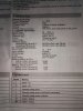
Here is schematic diagram of Gib thermostat hygrostat. What I want to do, is connect fan ventilate my grow room when temperature raise over 25C/77F and connect my ultra sonic humidifier on when humidity drops under 50%. Unlucky for me, I dont understand this schematic. Wich line goes where?

We use 230V AC in here.
Do I connect fan L to the number 3 and humidifier L to number 6? But how I connect fan N and humidifier N? To the wich number? Or do I pull new N line from wall plug for the fan N and humidifier N?
Please help old slow thinking pot head.
Electrician work isnt for me, but in here (damn near russia), we pot heads are popular as child molesters. Thats why I cant ask professional help. I have to be electrician, constructor worker, plumber and ventilation specialist.