DIY-HP-LED
Well-Known Member
VLR#2 Progress Report
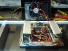
The LED panels have been applied, the rough wiring done and the major components mounted in the electrical box. Tomorrow I'll complete the wiring and fire it up for a quick bench test to check the components and wiring, before completion. Next I'll work on the top of the electrical box and mount the computer power connector to the rear of the box and cut holes for the 2 switches in the front. finally I'll sand and paint the box to before remounting the fan and mounting the switches and connector.
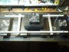
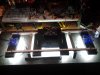
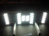
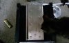
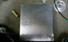
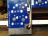
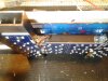
I lined the edges of the box where it mounts on the duct and cooling tubes with aluminum tape to seal it. I mounted the aluminum LED panels using washers and counter sunk 3mm screws salvaged from the street lamps, I also coated the backs of the panels with heat sink paste before applying them. Where the LED wires pass through the tubing, I used plastic strain relieving wire grommets and I enclosed the wires in plastic woven wire conduit salvaged from a computer power supply. I wire tied the woven conduit enclosed wires to the support frame and ran them to the inside cooling tube and from there to the duct, then electrical box. I had to extend the wires from the outside arrays to the electrical box using 4 conductor telephone wire (same gauge as that used to wire the arrays). All wire connections were soldered and covered with heat shrink tube, and in the case of the cooling tube LED panel wires, inclosed in woven conduit. I'm going to wire the 2 banks of LEDs so that alternate arrays will light in a checker board pattern at the low power setting.
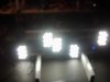
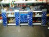
This 200W rig is composed of a total of 120, 3 watt LEDs divided into 10 arrays of 12 X 3 watt 5000K LEDs wired in series, if you were buying something like this, it would be advertised as a 360 watt lamp. The large panels are composed of 2 X 12 LED arrays and the 2 small panels in the center under the duct are composed of 12 LEDs each.
Here are a few photos of the build and various details.
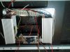
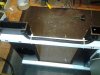
The LED panels have been applied, the rough wiring done and the major components mounted in the electrical box. Tomorrow I'll complete the wiring and fire it up for a quick bench test to check the components and wiring, before completion. Next I'll work on the top of the electrical box and mount the computer power connector to the rear of the box and cut holes for the 2 switches in the front. finally I'll sand and paint the box to before remounting the fan and mounting the switches and connector.
I lined the edges of the box where it mounts on the duct and cooling tubes with aluminum tape to seal it. I mounted the aluminum LED panels using washers and counter sunk 3mm screws salvaged from the street lamps, I also coated the backs of the panels with heat sink paste before applying them. Where the LED wires pass through the tubing, I used plastic strain relieving wire grommets and I enclosed the wires in plastic woven wire conduit salvaged from a computer power supply. I wire tied the woven conduit enclosed wires to the support frame and ran them to the inside cooling tube and from there to the duct, then electrical box. I had to extend the wires from the outside arrays to the electrical box using 4 conductor telephone wire (same gauge as that used to wire the arrays). All wire connections were soldered and covered with heat shrink tube, and in the case of the cooling tube LED panel wires, inclosed in woven conduit. I'm going to wire the 2 banks of LEDs so that alternate arrays will light in a checker board pattern at the low power setting.
This 200W rig is composed of a total of 120, 3 watt LEDs divided into 10 arrays of 12 X 3 watt 5000K LEDs wired in series, if you were buying something like this, it would be advertised as a 360 watt lamp. The large panels are composed of 2 X 12 LED arrays and the 2 small panels in the center under the duct are composed of 12 LEDs each.
Here are a few photos of the build and various details.
Last edited: