Data sheet for HLG rspec fr quantum board/general help
- Thread starter mscritch
- Start date

Reekwind
Member
The strips are 560x18mm.Im making an order today or tomorrow for sure, hoping to have everything built within two weeks so i can start flowering my currently vegging girls.
Still undecided whether i want to go h-influx or q series though. The q series is like over 200 cheaper, if its the same except more wiring, then I might as well go that route. I just need to make sure my wiring is correct. Ive drawn a diagram of course, thats how my brain works. Is this correct @Reekwind ? Obviously, this is only 2 lights, 1/3 of the total project. 3 strips per bar? How wide are the strips? I cant seem to find that. But i can shear my aluminum to whatever size, so i think 3 strips per bar will be good?
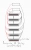
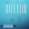
You can basically group the strips how you want but but keep light distribution in mind, if you space the strips evenly the light is weighted towards the center of the light. I suggest an uneven distribution.
I've shown the idea in the drawing below, obviously the strips would be a lot closer in the real build approx. same width and length. They're just spaced apart in the drawing to be able to see the wiring better.
The mixed connection build with Q-series powered by XLG 200 H-AB is done like this:

Okay, 60 q series strips and 6 XLG-200-H-AB drivers in hand. Working on making my frame in the next few days. I gotta still get thermal tape, pots, and plugs.The strips are 560x18mm.
You can basically group the strips how you want but but keep light distribution in mind, if you space the strips evenly the light is weighted towards the center of the light. I suggest an uneven distribution.
I've shown the idea in the drawing below, obviously the strips would be a lot closer in the real build approx. same width and length. They're just spaced apart in the drawing to be able to see the wiring better.
The mixed connection build with Q-series powered by XLG 200 H-AB is done like this:
View attachment 5366351
Will you guys verify this is the right shit?
Legrand-Pass & Seymour SA399WCC10 Residential Straight Blade Plug 15-Amp 125-volt Two Pole Three Wire, White https://a.co/d/5Ct8TKM
TWTADE / 3pcs Wh138 100k ohm Potentiometer Single Turn Rotary Linear Variable Potentiometer +3pcs black Aluminum alloy knob https://a.co/d/7grOPys
EDSRDRUS Thermal Adhesive Tape 0.8 Inches x 82 Feet High Performance Thermally Conductive Tape, High Durability, Apply for Heat Sink, LED Strips, Computer CPU, GPU,etc https://a.co/d/9xeUYZH
Also @Reekwind can you elaborate a little more on how to use the multimeter to get to the correct voltage? I think I know what you're saying; turn the pot on the driver down, connect leads from multimeter, turn up pot until multimeter hits correct current. I just want to make sure im correct in that thinking, what exactly that correct number is, and any other tips you may have?
Thanks again guys! Can't wait to post finished product pics
Reekwind
Member
AC plugs can just be bought in any hardware store.
Potentiometer must be 100K Ohm ( I usually use these for manual dimming https://rapidled.com/products/cased-potentiometer-with-knob - You can get them cheaper from Amazon/Alibaba etch. just do a google picture search.
Thermal tape look fine.
You also need wire for connecting the strips and driver, I recommend 18AWG solid core wire , it is super easy to stick into the connectors on the strips.
As well as some AC cable with 2 wires if you don't want to earth it, and 3 wires if you want to earth it. This should preferably be 14AWG (non solid)
Also 12x 5-por wago connectors and 6x 2-port wago connectors is needed, as well as connectors for the AC side e.g. https://rapidled.com/collections/wire-management/products/universal-wire-connector
When setting the drivers you need to wire everything, turn the potentiometer to max (max current) and then leave that alone.
Turn the internal potentiometer in the driver to 25-50% (under the bottom under a rubber cap - use small philps head screwdriver).
Then you turn it up until you hit the correct voltage. You can also just use a simple watt-meter and adjust to 200w, which is what you want to be your max.
sfw1960
Well-Known Member
If I couldn't save a bunch of money with DIY I wouldn't do it. If I was starting new today I'd still probably have a pile of HLG QB272 Rspec FR boards and some of the meanwell 480w drivers.
Built my own 60 amp x2 contactor box for switching the drivers safely too.
FWIW QB288's are discontinued and the 272 replaced it and they are only $35 each.

Built my own 60 amp x2 contactor box for switching the drivers safely too.
FWIW QB288's are discontinued and the 272 replaced it and they are only $35 each.
Okay guys, so I got the first (of six) lights wired up, but when god said let there be light, I instead got a let down. Does anyone have any idea why zero of the lights would turn on? I got 120 to the input on a voltmeter, but output was like .7 or something like that, regardless of either of the pots locations.
sfw1960
Well-Known Member
Ummm cuz it's probably not wired right?
Just a guess, which won't help anyone.
You probably should post pictures so we can clearly see the wiring, polarity and connections. The dimmer also as it can cause issues as well - everything please...

Just a guess, which won't help anyone.
You probably should post pictures so we can clearly see the wiring, polarity and connections. The dimmer also as it can cause issues as well - everything please...
Like the 3000k stuff I have a few posts up?It’s impossible not to, unless you grow with mono color and that’s gonna be a sad grow")
Last edited:
Reekwind
Member
Sounds like it's not correctly wired or there's a loose connection.Okay guys, so I got the first (of six) lights wired up, but when god said let there be light, I instead got a let down. Does anyone have any idea why zero of the lights would turn on? I got 120 to the input on a voltmeter, but output was like .7 or something like that, regardless of either of the pots locations.
Can you share a picture if how it's wired?
Reekwind
Member
No, 3000K is a broad spectrum, I mean mono diodes like 660nm.Like the 3000k stuff I have a few posts up?
I have 4x4 with 3000K only, and it's awesome
sfw1960
Well-Known Member
Just added 4 Rspec FR boards to one 4*8 but technically by definition 3000k is mono but sure is a broad spectrum and it seems people lose sight of the basics when looking...No, 3000K is a broad spectrum, I mean mono diodes like 660nm.
I have 4x4 with 3000K only, and it's awesome
There's a TON of blue and red in the 3000k and I only posted the spectrum on the Diablo X and a 4000k for the comparison of the two.
A single array of only one color LED probably wouldn't even grow anything unless you got lucky with a random color selection, so that gives clarity there!
@mscritch
We're waiting for pictures to help you out...
Jeffislovinlife
Well-Known Member
I have one of the HLG 600 Rspec. I run it in my flower tent don't know if it helps you the best of luck to you with all of your endeavor be looking forward to seeing what you do next

I run it in my flower tent don't know if it helps you the best of luck to you with all of your endeavor be looking forward to seeing what you do next Okay, so pics to come cause lifes been real busy and chaotic and i worked on it a bit but by the time i was done i had to go and didnt take pics.
Heres the things i tried:
I realized that both my positive and negative for my parallel were coming from my "input" strip, so i switched the negative to coming out of my "output" strip, and thats how the diagram showed it to be, but it still didnt work.
Then i tried wiring just one parallel with the series added. Still nothing.
Hmm. I just want any light, so I tried just one strip in parallel. Houston, i got light. So then i added another in parallel, both worked.
So then i wired them all in parallel, all worked, but seemed a bit weak. I checked with photonmeter and was only getting 600 ppfd at about a foot away, so im pretty sure putting them all in parallel makes them underpowered. Makes sense for the series/parallel combo wiring.
So, it pretty much has to be an issue with that combo wiring. Any guesses what it could be? Ill add pics hopefully later today
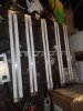
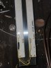
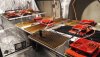
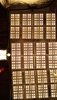
Okay, heres pics the best i can. The first one is a whole view.
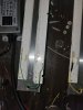
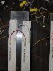
The next two are showing where the negative was switched to the "output" strip, the other end in the pic tying the strips together is wired parallel because that was my last attempt, which did not work, but i also tried it with just one jumper in series pos to neg like the next pictures. The next pictures show wired i believe exactly as the diagram from Reekwind, which didnt work. Only way they work is wired in parallel all the way.
Rocket Soul
Well-Known Member
@mscritch
Youre trying to do this right?
Its hard to see cause theres no pics where both ends of the strips can be seen, the connections of the top part depends on how its wired on the bottom.
The current needs to follow the following path on every string of 2 strips in series:
1 Driver + to + first strip (here it seems like the left one)
2 from first strip - to second strip + (here looks like the one on the right) : this you got right in the bottom pic, but if you check i think its the third one from the top, you have + to + and then - to-, not correct! No need for 2 cables, and you need to go from minus first strip to + second)
3 from second strip - to driver minus.
Driver + and driver -: in order to connect them in a group of string youd need a wago here on both sides.
Reekwind
Member
View attachment 5373646View attachment 5373647View attachment 5373648View attachment 5373649View attachment 5373650
Okay, heres pics the best i can. The first one is a whole view.
The next two are showing where the negative was switched to the "output" strip, the other end in the pic tying the strips together is wired parallel because that was my last attempt, which did not work, but i also tried it with just one jumper in series pos to neg like the next pictures. The next pictures show wired i believe exactly as the diagram from Reekwind, which didnt work. Only way they work is wired in parallel all the way.
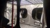
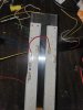
At the top of the left pair of strips with two wires + to + and - to - has to be only a single wire + to -
The wire from the driver's + output must go in to the bottom + port of the strip that has the + connected at the top. Same deal with the minus side.
All respective +'s connected between strips and driver in a 5 port Wago connector. Same deal with minus side.
I can see that the two strips on the left are facing the same direction while the other pairs' directions are alternating, this kind of inconsistency makes it very easy to mix up + and -
It would help a lot if we could see the wiring from the driver to the strips as well.
I got it! I was being a dummy. I shoulda known that my brain just farted i think with the parallel and I went into panic mode lol all i had to do was go - to + for the series. Thank you guys! That was only the first of six so ill get more pics when i have them all built and wired up!