Cree CXA analysis

caretak3r

Well-Known Member
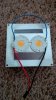
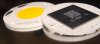
I ordered 4 Vero13s, I'm going to place them 2 per arctic 11 plus CPU cooler. I'm going to drive 2 Veros per LED driver. So 4 lights, 2 heatsink/fans, 2 drivers. This was the most cost effective solution I could come up with - $55 for high CRI 3000K Vero13 from digikey (shipped), $20 for the 2 heatsinks shipped, $26 for 2 x DC36-75V 680mA drivers shipped (yes I'm going to run them a bit hot)... So that's a total of roughly $100 all inclusive.

Now, my question is whether the Arctic Alumina thermal adhesive I have will be sufficient if I clamp them down while drying or whether i truly need to drill and tap the heatsinks?
 

MrFlux

Well-Known Member
There is no need for drilling and screwing, the Arctic epoxy bond is extremely strong by itself. Another option is silicon glue, it's still strong enough but offers a chance to remove the the parts from the heatsink should the desire ever arise.

I like everything about the project except the high CRI :evil:
 

caretak3r

Well-Known Member
There is no need for drilling and screwing, the Arctic epoxy bond is extremely strong by itself. Another option is silicon glue, it's still strong enough but offers a chance to remove the the parts from the heatsink should the desire ever arise.

I like everything about the project except the high CRI :evil:
that was just because of what was available to ship at the time. Hopefully won't make a ton of difference. -- this is what I got: http://www.digikey.com/product-detail/en/BXRC-30H2000-C-03/976-1166-ND/3913143
 

MrFlux

Well-Known Member

SupraSPL

Well-Known Member
Mr Flux, my spreadsheet to calculate efficiency depends on an understanding of what happens to the LED at a given operating temperature and current. I understand that as the LED junction temp rises, the vF decreases slightly. This vF drop is especially noticeable on long strings of LEDs. The way I am calculating it, this actually increases efficiency very slightly (independent of the losses from temp droop). So power consumption decreases slightly while output remains the same. Am I understanding correctly or is there an additional decrease in output due to that decrease in vF?
 

SupraSPL

Well-Known Member
DIYers take care when you are mounting COBs. The efficiency and longevity of the design is utterly dependent on a very low thermal resistance (.3 degrees/watt) because we are running a lot of watts in a small package. Any hiccup in the thermal path can add several degrees per watt and the heatsink itself has a thermal resistance. Even though they may appear polished, aluminum heatsink surfaces are not flat. They would need to be sanded flat and you might as well lap and polish it while you are bothering. Any thermal interface compound that includes an adhesive will perform poorly compared to one that does not. Good luck and keep them cool :)
 

smokey the cat

Well-Known Member
I'm pretty impressed with the adhesive that I got from StevesLEDs.

I remounted a V-18 as the initial contact didn't feel great - I lifted it up after setting and you could see that only a quarter of the LED patch was making proper contact with the sink. Be careful and clamp well.

I ended up using gym plate weights to provide clamping force. The centre hole in my weights fitted nicely around the edge of the bezel - and flexed it flat to the sink. I stacked 8kg on each for 24hr of setting.

I don't have a temperature probe at the moment, but running ~1600ma without a fan the emitters pour a lot of heat into the aluminum - heating it to 50*C+ in a few mins. This is a big 700g heatsink, so definitely a fair bit of thermal mass.

The quality of the finish on my V18 contact patch wasn't great either - rougher than a typical CPU heatspreader. It'd be difficult to lap though unless you used a tiny powered polisher or something. First of you LED nerds to give it a go wins a cookie :)
 

MrFlux

Well-Known Member
So power consumption decreases slightly while output remains the same. Am I understanding correctly or is there an additional decrease in output due to that decrease in vF?
What you are finding is a real effect. Temp goes up, Vf goes down, current and hence number of light quanta remains the same. The same 'output' for less power, right?

In terms of quantum flux: yes but in terms of power: no. While the number of photons stays the same, the average energy per photon goes down with Vf: The blue peak will shift slightly in the spectrum towards the red. The net result is that there is less light power going out, and that the radiometric efficiency of a LED always decreases as the temperature goes up.
 

MrFlux

Well-Known Member
Don't forget that a COB has a large contact area, which makes for very effective cooling.

To take a worst case scenario:

Emitter: Vero 13, area A, diameter D = 36mm, Q = 30W heat (that is a overdriven vero)
Glue: k = 0.5 W/m/K (that is a shitty conductor)
Gap: dx = 0.25mm (that is a wide gap)

dT = Q . dx /(k . A) = 3.7 Celsius
 

SupraSPL

Well-Known Member
In terms of quantum flux: yes but in terms of power: no.
Great info thanks! Based on what you are saying I should leave the spreadsheet as is.

Regarding the cooling issue, I recall that an LED professionally reflowed to a typical 20mm star adds 2degrees/watt in addition to the 2.5-5 degrees per watt of internal thermal resistance in the LED itself. So the COB has improved that number down to .3 degrees/watt which is phenomenal. Another advantage for COB is that white/blue LEDs are much less sensitive to temp droop than reds. They also tend to have much lower internal thermal resistance than reds.

So Mr Flux is your equation suggesting that a poor thermal interface is only adding 3.7 degrees to the junction temp or is it adding 3.7 degrees/watt? (Sorry equations make my head explode even when I read my own equations.) Once we are past that stage I wonder how the thermal resistance of the heatsink itself will affect the Tj of a COB? For the example you gave above, could you estimate what the Tj of that emitter would be, assuming an adequate heatsink and reasonable ambient temp?

Smokey I am using 110cm2/watt for passive cooling to end up with 30C heatsink temp. If you have the dimensions of the heatsink you are using I can put it in the spreadsheet to give you an idea where you are at.
 

Wyckoff

Member
MrFlux -

I'm interested in understanding this technology with the same depth you have. I barely understand what is being discussed here and I definitely could not duplicate your incredible analysis. Could you tell me how you gained your knowledge set? Are there any texts, videos or websites you would recommend for diving into this material?
 

caretak3r

Well-Known Member
I only had 320 and 400 grit sandpaper so I did what I could - it was a vast improvement over how it started so I'm happy with the results.

Every time I look at this it makes me laugh :)IMG_00000022.jpg
 

caretak3r

Well-Known Member
forgot to mention, with a 700ma driver, it's pulling 43W at the plug. Also, you'll notice they slid around a bit, however the metal pads are fully covered by the heatsink even though some plastic hangs over the side. The 2nd one I did a better job.
 

Abiqua

Well-Known Member
MrFlux -

I'm interested in understanding this technology with the same depth you have. I barely understand what is being discussed here and I definitely could not duplicate your incredible analysis. Could you tell me how you gained your knowledge set? Are there any texts, videos or websites you would recommend for diving into this material?
Ive been watching any relevant podcasts from this dude:
http://www.youtube.com/user/EEVblog
 

smokey the cat

Well-Known Member
Showing the bottom of Vero - flat but not that smooth.
DSC08026.jpg

The sink surface below is pretty well lapped - went up to 1200grit then a little liquid metal polish to shine it up.


Supra - the sink I'm using is a 100x182mm sink with 19 fins that extend 40.35mm above the base. Been a while since highschool maths, but I total 171530mm^2 of top surface area [made from 19x fin area on vertical plane (= 40.35*2*100 ; and including top surface on horizontal plane (100x182). This is cheating a bit and treating the fins being made with perfect 90* angles to avoid becoming a trig problem. I'm too old to bother with a hypotenuse lol, so this number will be a tiny bit lower than actual top surface area...
 

MrFlux

Well-Known Member
So Mr Flux is your equation suggesting that a poor thermal interface is only adding 3.7 degrees to the junction temp or is it adding 3.7 degrees/watt? (Sorry equations make my head explode even when I read my own equations.)
It's 3.7 degrees total; This is the temperature difference between the back of the Vero and the face of the heatsink. The equation used is not so scary at all, it's called Fourier's law.

Once we are past that stage I wonder how the thermal resistance of the heatsink itself will affect the Tj of a COB?
That totally depends on the heatsink and its environment, but it's not different from using single emitters. The intuition you have build up there works for COBs too.


I'm interested in understanding this technology with the same depth you have. I barely understand what is being discussed here and I definitely could not duplicate your incredible analysis. Could you tell me how you gained your knowledge set? Are there any texts, videos or websites you would recommend for diving into this material?
Wyckoff, if the curiousity is there then the knowledge that you need will follow. I like to always have some sort of project going, this leads to more experience and then to the next project.
 

SupraSPL

Well-Known Member
Mr Flux, can we recruit your help on this one? If I understand PAR watts correctly (total photon energy from 400-700nm, otherwise unweighted), it seems impossible that a 1000W HPS can create 535 PAR watts, I would expect more along the lines of 400. This site for example is also claiming that number and also claiming that a 1000W metal halide can create 581 PAR watts.
 

SupraSPL

Well-Known Member
Thanks for the pic smokey and nice work lapping the sink.

If I assume your the riser of your heatsink is .4cm and the fins are running the long way, I get 3166cm2. That is good for 23w is you run it hard and 27w if you run it soft. If I assume the fins are on the short side I get 1903cm2 which is close to your number. Good for 14w hard and 16w soft.

I based those numbers on (aggressive passive cooling)
135cm2/watt if the led is at 26% efficient
110cm2/watt of the led is running at 42% efficient

Depending on how hard you run the Vero18 will be 30-34% efficient and dissipate 20-40w.
 
Top