For everyone that has some of these and needs the technical info, chilled pulled it off their website so finding this has been a real pain in the arse.
Enjoy
Oh yeah, nice little 'secret'... not sure about the 90W PCBs but on the 175W PCBs you can actually run the white channels at 1400mA instead of 1050mA. That makes it a 207W PCB.
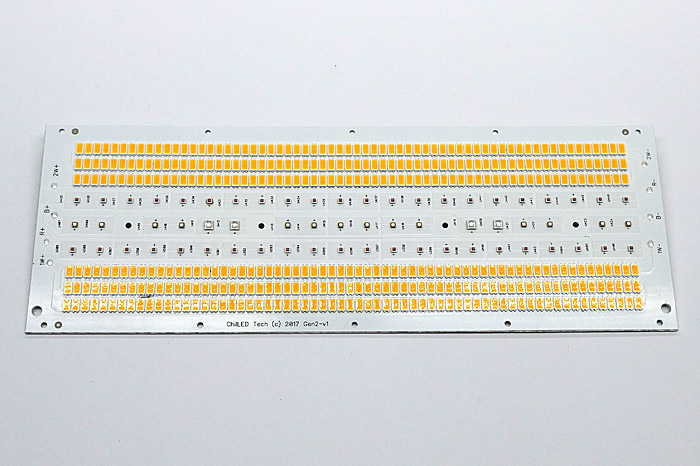
High efficiency 175W Gen 2 LED grow light PCB pictured
2.67 – 2.97 μmoles/joule
LED Chips Used on Gen 2 Max Yield PCBs
How Many Boards Do I Need For My Area?
The number of boards you need will depend on what photon flux (light intensity) you are looking to achieve per given area.
If you are not supplementing with CO2 and are growing a fruiting/flowering crop, then stay around 900-1,000 micromoles.
If you are supplementing with CO2 and are growing a fruiting/flowering crop, then you can go up to 1,200-1,400 micromoles.
Note: Adjust your room air temperature higher under LED lighting, about 85 degrees fahrenheit and 90 degrees under high light/CO2 conditions.
EXAMPLE: Your area is 4ft by 4ft and you want 1,000 micromoles PPFD, 4ft x 4ft = 16 square feet.
175W PCBs: 16 square feet x 0.238 PCBs per square foot = 3.808 PCBs, round to nearest whole number = 4 175w PCBs needed to get 1,000 micromoles PPFD average in 4 x 4ft (16sq ft) area.
90W PCBs: 16 square feet x 0.476 PCBs per square foot = 7.616 PCBs, round to nearest whole number = 8 90w PCBs needed to get 1,000 micromoles PPFD average in 4 x 4ft (16sq ft) area.
175W LED PCB (At 1050mA drive current) – System Level
Factored total losses of 18.5% (about 2.2um/j @ wall, to be conservative)
90W LED PCB (At 1050mA drive current) – System Level
Factored total losses of 18.5% (about 2.2um/j @ wall, to be conservative)
Which PCB Do I Need, 175W or 90W?
For small areas and even light coverage, it is better to use more boards of lower wattage (90W).
For large areas it’s more economical to use less boards of higher wattage (175W) and still get even light coverage.
What Hanging Height Should I Use?
For small areas: 18-24in
For large areas: 24in or higher if ceiling height allows it.
What PCB Spacing/Arrangement Do I Use?
Space boards evenly within your canopy for best light coverage.
Which Drivers Do I Need?
Each PCB color channels wired in series, use table below:
Enjoy
Oh yeah, nice little 'secret'... not sure about the 90W PCBs but on the 175W PCBs you can actually run the white channels at 1400mA instead of 1050mA. That makes it a 207W PCB.
High efficiency 175W Gen 2 LED grow light PCB pictured
2.67 – 2.97 μmoles/joule
LED Chips Used on Gen 2 Max Yield PCBs
- Samsung LM561C 3000K S6
- Lumileds Luxeon C Red
- Lumileds SunPlus 20 Deep Red
- Lumileds SunPlus 20 Royal Blue
- Everlight EAUVA35352
How Many Boards Do I Need For My Area?
The number of boards you need will depend on what photon flux (light intensity) you are looking to achieve per given area.
If you are not supplementing with CO2 and are growing a fruiting/flowering crop, then stay around 900-1,000 micromoles.
If you are supplementing with CO2 and are growing a fruiting/flowering crop, then you can go up to 1,200-1,400 micromoles.
Note: Adjust your room air temperature higher under LED lighting, about 85 degrees fahrenheit and 90 degrees under high light/CO2 conditions.
EXAMPLE: Your area is 4ft by 4ft and you want 1,000 micromoles PPFD, 4ft x 4ft = 16 square feet.
175W PCBs: 16 square feet x 0.238 PCBs per square foot = 3.808 PCBs, round to nearest whole number = 4 175w PCBs needed to get 1,000 micromoles PPFD average in 4 x 4ft (16sq ft) area.
90W PCBs: 16 square feet x 0.476 PCBs per square foot = 7.616 PCBs, round to nearest whole number = 8 90w PCBs needed to get 1,000 micromoles PPFD average in 4 x 4ft (16sq ft) area.
175W LED PCB (At 1050mA drive current) – System Level
Factored total losses of 18.5% (about 2.2um/j @ wall, to be conservative)
| Your Target PPFD | 175w PCBs Per Square Foot | 175w PCBs Square Meter |
| 1,400 | 0.333 | 3.58 |
| 1,200 | 0.285 | 3.07 |
| 1,000 | 0.238 | 2.56 |
| 800 | 0.190 | 2.05 |
| 600 | 0.143 | 1.53 |
| 400 | 0.095 | 1.02 |
| 200 | 0.048 | 0.51 |
90W LED PCB (At 1050mA drive current) – System Level
Factored total losses of 18.5% (about 2.2um/j @ wall, to be conservative)
| Your Target PPFD | 90w PCBs Per Square Foot | 90w PCBs Square Meter |
| 1,400 | 0.667 | 7.18 |
| 1,200 | 0.572 | 6.15 |
| 1,000 | 0.476 | 5.13 |
| 800 | 0.381 | 4.10 |
| 600 | 0.286 | 3.08 |
| 400 | 0.191 | 2.05 |
| 200 | 0.095 | 1.03 |
Which PCB Do I Need, 175W or 90W?
For small areas and even light coverage, it is better to use more boards of lower wattage (90W).
For large areas it’s more economical to use less boards of higher wattage (175W) and still get even light coverage.
What Hanging Height Should I Use?
For small areas: 18-24in
For large areas: 24in or higher if ceiling height allows it.
What PCB Spacing/Arrangement Do I Use?
Space boards evenly within your canopy for best light coverage.
Which Drivers Do I Need?
Each PCB color channels wired in series, use table below: