Bridgelux Vero 29 LED Test
- Thread starter PICOGRAV
- Start date
PICOGRAV
Well-Known Member
Nope, I have a huge fan drawing fresh air in constantly, I would say the all the air in the room 850 Sq ft is changed once every 10-20 min. I am thinking that this is helping them grow much better as well.Looking good. How's the odor? House stink yet?
PICOGRAV
Well-Known Member
Haha, yeah I ask people because maybe I cant detect it, but the funny thing is half the people in my building grow so my stink aint even that bad compared to the other lol. I think my neighbor is at the start of flowering.Have you had anyone over recently that doesn't frequent your house often? That's the true test")
Green in The Garden
Member
I think my neighbor is at the start of flowering.
ha ha ha ha.. lol..


Pico- Got my HP power supply from storage today. Flipped it on and got massive fan noise. Pulled it apart and sure enough the blade was completely loose and the motor was shot. Felt like I was spinning the motor around gravel. I'm now looking into another AC fan since I can't replace it with a cheap PC fan. They are dc from what I remember.
Also noticed the volt meter does not move. The amp gauge does.
This is one of those moments I wish I knew hardware level circuitry.
Also noticed the volt meter does not move. The amp gauge does.
This is one of those moments I wish I knew hardware level circuitry.
PICOGRAV
Well-Known Member
So the first thing I need to see is the full back panel, you and get replacement AC fans you have to just be careful when rewiring them coz they run at 120v ~.Pico- Got my HP power supply from storage today. Flipped it on and got massive fan noise. Pulled it apart and sure enough the blade was completely loose and the motor was shot. Felt like I was spinning the motor around gravel. I'm now looking into another AC fan since I can't replace it with a cheap PC fan. They are dc from what I remember.
Also noticed the volt meter does not move. The amp gauge does.
This is one of those moments I wish I knew hardware level circuitry.


Connecting your multimeter in a wrong way and it can blow it up in your face....make sure to put the "sensor"cables in the correct connectors and to Switch wether to amps and voltage accordingly, also usually there r 2 different fuses 10A and less. Also its not hard to find how to measure voltage (in parallel) and amps (in series) to your circuit in the wwwAlso noticed the volt meter does not move. The amp gauge does.
PICOGRAV
Well-Known Member
I think he was talking about the voltmeter on the power supply, most likely its the sense connections set up for parallel operation or remote sense, the strange thing is that the amp gauge is moving...Connecting your multimeter in a wrong way and it can blow it up in your face....make sure to put the "sensor"cables in the correct connectors and to Switch wether to amps and voltage accordingly, also usually there r 2 different fuses 10A and less. Also its not hard to find how to measure voltage (in parallel) and amps (in series) to your circuit in the www
Correct. I was referring to the voltmeter on the power supply itself.I think he was talking about the voltmeter on the power supply, most likely its the sense connections set up for parallel operation or remote sense, the strange thing is that the amp gauge is moving...
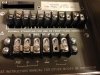
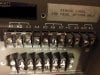
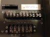
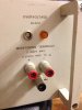
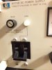
For testing with the multimeter: I used the positive and negative lead that is on the front of the device. If that is incorrect, do let me know. I was able to get the correct amp reading as it matched the reading on the power supply. The Voltmeter on the device works when I remove the leads from the positive and negative post on the front and the amps then read zero. I am most likely doing this wrong. I have not touched a multimeter in 15 years.
Now for pictures of the device.
PICOGRAV
Well-Known Member
So the sense connections are missing, let me check the data sheet to see what to connect "S-" and "S+"...Correct. I was referring to the voltmeter on the power supply itself.
For testing with the multimeter: I used the positive and negative lead that is on the front of the device. If that is incorrect, do let me know. I was able to get the correct amp reading as it matched the reading on the power supply. The Voltmeter on the device works when I remove the leads from the positive and negative post on the front and the amps then read zero. I am most likely doing this wrong. I have not touched a multimeter in 15 years.
Now for pictures of the device.
View attachment 2883783View attachment 2883784View attachment 2883781View attachment 2883769View attachment 2883771
http://cp.literature.agilent.com/litweb/pdf/5950-1765.pdf
The data sheet tells you what terminals need to be jumped for normal operation...
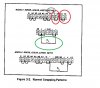
Make the to links in red, the "S-" and "S+" are the sensing inputs for the voltage regulators, that's why there was no voltage read out, you connect them to a true output of the power supply, before the final load, "A9" and "A10", having these out puts let you link them to together in series or parallel operation, this explains the clearly marked 120 maximum output and the true ground tap. It also allows you to control the output voltage through, say a external source like a computer... The array of other terminals are for ampere control linking, bit more complex.
So make the links in red and you load (LEDs) connect in the green, the resistor.
Follow up on testing of the power supply. I was using the multimeter wrong. Did not swap the red lead like I should have. Thank you world wide web.
I do not mean to thread hijack as I have many more questions in regards to the power supply. I would gladly take this into PM Pico if you prefer.
I do not mean to thread hijack as I have many more questions in regards to the power supply. I would gladly take this into PM Pico if you prefer.
PICOGRAV
Well-Known Member
You can post in my other thread I have going,
https://www.rollitup.org/led-other-lighting/740283-picos-diy-thread-advise-ideas.html
I don't mind, really but feel free to PM
https://www.rollitup.org/led-other-lighting/740283-picos-diy-thread-advise-ideas.html
I don't mind, really but feel free to PM
PICOGRAV
Well-Known Member
Lax you're a great guy.better to post it openly so others could learn from it
I agree. Just didn't want this thread to turn into troubleshooting of my own power supply. I will keep it open in the other thread that is more for the DIY.better to post it openly so others could learn from it
PICOGRAV
Well-Known Member
Did you guys think you would really go 3 days with out an update ")
Today was the water only day and I decided that's all they are going to get until the chops,


You can see the buds in the canopy are also doing very well,


My double tap root idea didn't work, but the clone is going well,


And today the first components of the next grow test arrived, 2 foot by 6 by 86 inch tall rack, with 2x2 extension,
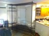
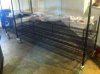
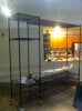
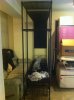
It'g going to be a hybrid hydro grow, with 6 Bridgelux Vero 29s LEDs, more to come soon...
Today was the water only day and I decided that's all they are going to get until the chops,
You can see the buds in the canopy are also doing very well,
My double tap root idea didn't work, but the clone is going well,
And today the first components of the next grow test arrived, 2 foot by 6 by 86 inch tall rack, with 2x2 extension,
It'g going to be a hybrid hydro grow, with 6 Bridgelux Vero 29s LEDs, more to come soon...
Green in The Garden
Member
cool project..