DiY LED - Cree CXA3070

stardustsailor

Well-Known Member
I hate to disagree with you but I have designed and built linear power supplies and even rewound transformers fro old microwave ovens and linear power supplies are not efficient. they are designed to produce a clean stable output. PWM voltage or current regulation is much more efficient. just compare the size of the heatsink on both types of power supplies to see how much heat they are designed to dissipate.constant current would be better because the forward drop decreases as the temperature goes up and with constant voltage well regulated supplies this can lead to thermal runaway that could destroy the diode. constant current supplies track this voltage drop so total input power declines as temperature rises. providing some protection for the diode.
No matter if Linear or Switching .
Constant Voltage Output Power Supplies ,are not ideal for driving leds.
Neither PWM voltage is ideal .
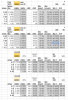
Leds should be driven(powered) with a Constant Current regulation ,as their Vf changes dramatically depending on diode's junction temperature .

So for example if at Tj =25C (say ambient/room temp) a led driven at 1000mA ,has a Vf of 30 V ..
If the junction temperature rises to 85C ,for the same amount of current to pass through ,the diode now has a Vf of
22 V ...
If a CV power supply is used ,the power supply will continue to apply a 30 V voltage to the led ...
The current passing through the diode will be way more than 1000mA ..
The led will overheat ,which will lead to even lower Vf ,thus higher current passing .
The led will soon get fried ....


If a CC power supply was used instead ,the power supply will 'sense' the drop of led's Vf
(as it tracks changes at circuit 's overall "resistance' ) and lower the output voltage to 22V ,
so tghat 1000mA will continue to pass through the led ...
The led will soon stabilise to a stable operating state,electricall-wise ..

As for the type of voltage regulation used for CC led drivers ,is almost always the switching type ..
Which is much more efficient (thus runs cooler,needs smaller heatsinks/transformers ) and compact sized ..
But it has a 'filthy ' output ,full of ripple 'noise' ..
And contaminates with noise the mains AC ..

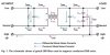
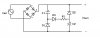
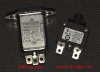
SDS's advice : Use an EMI filter at the AC inlet of Switching power supplies .
It somewhat 'cleans' lots of ripple noise at their output ..
And reduce the contamination to the AC mains .
http://www.schaffnerusa.com/en/technical-library/emc-emi-filters.html
http://www.schaffner.com/en/products/emcemi.html


SupraSPL

Well-Known Member
Awesome discussion guys. I have a bunch of constant current drivers that are very efficienct but have a poor power factor ~.5. I was thinking about connecting a capacitor in parallel to move the circuit closer to parity. Is that what this plug (above) does, active power factor correction?
 

SupraSPL

Well-Known Member
This thing bugs into a 20A breaker slot and adds active power factor correction to the whole house. They claim it will save you $ on your power bill, but it will not LOL
 
Last edited:
Hey Supra,

Haven't been around really as I have had a couple things in life to attend to. You are correct, the 33.30 price in multiples of 20 is from Arrow, as some others have found and posted.

Bridgelux updated their data sheets in February and have posted information regarding the operating characteristics of their Vero lineup at 85C.

I just went through it, and it looks like, on paper anyways, the 4K Vero 29 and the 3K 3070 are within fractions of a percentage of each other.

Original plan was 3070s on HLG-185H-C1050 @ .525 - 1.05 = about 178 V

Thinking of vero 29s on HLG-185H-C1400 @ .7 - 1.4 = about 146 V

Price is basically the same. Vero offers better CCTs however.

What are your thoughts on the updated Vero datasheets? It seems like some of the information contradicts itself. I see a 16% gain in efficiency quoted in one table from 85 to 25 tc, yet in a graph in the document, it illustrates a 10% difference.

I don't know if I can trust Bridgelux :D

Here's the document; http://www.bridgelux.com/wp-content/uploads/2014/02/DS33 Bridgelux-Vero 29 LED-Array-Data-Sheet 2014.02.03.pdf
 

SupraSPL

Well-Known Member
Thanks for the heads up, I did not know there were updates to the Vero29 sheets. I guess the next question is, were there updates to the LEDs as well?

When comparing LEDs I always use the "minimum" flux figures and "typical" vF figures. Based on the numbers in the sheet you linked, here is how they stack up at Tj 50C:
CXA3070 3000K Z4 @ 1.4A = 52W @ 39.3% efficient
Vero29 3000K @ 1.4A = 51W @ 35.8% efficient
Vero29 4000K @ 1.4A = 51W @ 37.1% efficient

If you ran the CXA3070 at 1050mA, 38W @ 42.4% efficient

I see what you mean regarding the inconsistencies. The Vf chart doesnt match up with the data in the tables. I used the data in the tables because Tj is specified. It also seems strange that they don't have flux bins.
 

stardustsailor

Well-Known Member
Awesome discussion guys. I have a bunch of constant current drivers that are very efficienct but have a poor power factor ~.5. I was thinking about connecting a capacitor in parallel to move the circuit closer to parity. Is that what this plug (above) does, active power factor correction?

EMI/ RFI Filters :

(...)Within switch-mode power supplies, a high dc voltage is chopped or switched at a high frequency that
can range from 50 kHz to 1 MHz.This high-speed switching process is intrinsic to switch-mode power supplies and provides its improved efficiency and reduced size when compared to linear power supplies.
However, as a side effect, this switching generates unwanted EMI. Infact, most conducted EMI within switch-mode power supplies originates from the main switching MOSFETs,transistors, and output rectifiers.
In either power supplies or electronic equipment, it is the function of the EMI filter to keep any internally generated noise contained within the device and to prevent any external ac line noise from entering the device. EMI filters usually comprise a network of passive electronic components including capacitors and inductors that form L-C circuits.
Since unwanted EMI is at much higher frequencies than normal signals, the EMI filter works by selectively
blocking or shunting unwanted higher frequencies. Basically, the inductive part of the EMI filter is designed to act
as a low-frequency pass device for the ac line frequencies
and a high-frequency blocking device.Other parts of the EMI filter use capacitors to bypass or shunt unwanted
h i g h - f r e q u e n c y noise away from the sensitive circuits.
The net result is that the EMI filter significantly reduces or attenuates any unwanted noise signals from entering or leaving the protected electronic device.(...)

Emi filter.JPG
http://us.tdk-lambda.com/ftp/other/all_about_emi_epmag.pdf

.................................................................................................................................
Also ,an EMI filter serves as a " high current /surge protection "..
If a high current spike comes from the mains line towards the leds ,firstly
it will have to enter the led light fixture/circuit through the EMI filter ..
Which has a nominal operating current ...
The device's components (coils/capacitors) will fry ,almost instantly ...
Thus reducing or completely blocking ,the incomming current spike ,from rushing to led drivers
and from there to led(s)....


Passive PFC :
(...)
Passive PFC
The simplest way to control the harmonic current is to use a filter: it is possible to design a filter that passes current only at line frequency (50 or 60 Hz). This filter reduces the harmonic current, which means that the non-linear device now looks like a linear load. At this point the power factor can be brought to near unity, using capacitors or inductors as required. This filter requires large-value high-current inductors, however, which are bulky and expensive.
A passive PFC requires an inductor larger than the inductor in an active PFC, but costs less.

This is a simple way of correcting the nonlinearity of a load by using capacitor banks. It is not as effective as active PFC. One example of this is a valley-fill circuit.

The Valley -fill circuit ...valley-fill.JPG
(...) At start-up, the rectified line voltage is applied across C1 and C2, as they are both charged via D3 and R1, until C1 and C2 are each charged up to approximately half of the peak line voltage. When the line voltage falls into the "valley" phase, Vout begins to fall toward half of the peak line voltage. At this point, C1 and C2 begin to discharge into the load at Vout, via D1 and D2 respectively.An advantage of this design is that it is rather simple. A disadvantage is that the ripple voltage can still be 50% of peak, and have total harmonic distortion (THD) of 35%, which is rather high.
(...)


From what I understand the emi filter is at the AC side ..
While the PFC is on the DC side ...

Still it seems that the EMI filter does some Power Factor correction ,also ...
 
Last edited:

stardustsailor

Well-Known Member
My new CXA 3070 design ,will use the HLP-80H-42 drivers from meanwell ...
http://www.meanwell.com/search/HLP-80H/default.htm
Soon to be released on the market ...I'll have to wait ...

Which ,by the way ,is 99% sure, that is the ' internals ' of the top-notch
HGL-80H-42 ,at half the price !!
( approx 36 Euros for the HLP-80H-42...Approx 75 Euros for the HGL-80H-42... )
http://www.meanwell.com/search/HLG-80H/default.htm
(Although I don't get the 1% ( ! ) efficiency difference ! )


And meanwell offers a 20kA surge protection ...
http://www.meanwell.com/search/SPD-20/default.htm


Well ..I'm going to use a simple,cheap ( ~$10 total ) and effective method ....

An AC inlet/EMI filter and a resettable circuit breaker ...
basic protection.jpg
 
Supra,

I haven't done any pixel counting and haven't tested the COBs in person yet, but my quick numbers don't seem to add up with yours. I may be missing something, but here is what I gather from the datasheets of these two at 2100ma and 1925ma respectively;

Vero 29 4k (closest to the cree 3k)

VF (typ 85c) 36.8
Flux (min 85c) 8060
Watts 77.28
lm/w 104.29

3070 z2 3k (z4 is almost impossible to source)

VF (typ 85c) 38.5
Flux (min 85c) 7390
Watts 74.13
lm/w 99.71

I am assuming both would gain in equal amounts when under driven and ran cooler.

Have I made a mistake in my reasoning?


Thanks for the heads up, I did not know there were updates to the Vero29 sheets. I guess the next question is, were there updates to the LEDs as well?

When comparing LEDs I always use the "minimum" flux figures and "typical" vF figures. Based on the numbers in the sheet you linked, here is how they stack up at Tj 50C:
CXA3070 3000K Z4 @ 1.4A = 52W @ 39.3% efficient
Vero29 3000K @ 1.4A = 51W @ 35.8% efficient
Vero29 4000K @ 1.4A = 51W @ 37.1% efficient

If you ran the CXA3070 at 1050mA, 38W @ 42.4% efficient

I see what you mean regarding the inconsistencies. The Vf chart doesnt match up with the data in the tables. I used the data in the tables because Tj is specified. It also seems strange that they don't have flux bins.
 

SupraSPL

Well-Known Member
Wow awesome info tnx SDS! I will have to do some studying to grasp all that. I love that driver too ( for photography) but is running harder than I like to for growing.

Overthinkingismything, I will get back to you on that in a sec
 
Yes, I've seen those and the used z2s up for auction. Does anyone know if they are a forum member somewhere? I'd like to conduct business outside of ebay if possible. I'm a bit apprehensive about getting an item shipped internationally that is marketed as a grow light in the description and paypal having a record of that.

Do you guys worry about ordering high power LEDs and PSUs to your residence? Or does everyone grow in a seperate dedicated location? Or am I just being overly cautious and paranoid (I'm not sure that's possible).

I'm thinking LEDs, PSUs, pumps, bulkheads, tubing, heatsinks, variacs all coming in the mail doesn't look too good to those who monitor such things... I've been able to procure all the other things out of town, luckily.

Awesome, thanks Supra! I'm thinking if the numbers are in the veros favor - or if it's a wash - that the 3500K vero may be interesting :)

Wow awesome info tnx SDS! I will have to do some studying to grasp all that. I love that driver too ( for photography) but is running harder than I like to for growing.

Overthinkingismything, I will get back to you on that in a sec
 

Chronikool

Well-Known Member
Do you guys worry about ordering high power LEDs and PSUs to your residence? Or does everyone grow in a seperate dedicated location? Or am I just being overly cautious and paranoid (I'm not sure that's possible).

I'm thinking LEDs, PSUs, pumps, bulkheads, tubing, heatsinks, variacs all coming in the mail doesn't look too good to those who monitor such things... I've been able to procure all the other things out of town, luckily.
I think the authorities are looking for HID bulbs and 'classic' grow lamps, etc....DIY LED's are probably a bit new for their radars...already made grow panels i wouldnt know...

These modules can be used for a variety of sources...so i wouldnt worry :) They are whites after all....not your olde' school reds and blues
 

Observe & Report

Well-Known Member
A Z4 3kK 3070 puts out 7945lm and a Z2 7390 at 1.925A, a 7.51% difference. DigiKey has Z2's for $40 and Z4's are on eBay for $54, ignoring shipping. If you're running them for 12 hours a day at $0.15/kWh, then 7.51% amounts to $3.66 annually, so it's going to be almost four years before you start reaping efficiency benefits at the marked up price.
 

SupraSPL

Well-Known Member
O&R, thanks for the heads up on that I did not know Digikey got Z2s back in stock, very cool.

Regarding Z2 vs Z4, the Z4 is has about 3% higher radiometric efficiency, a 7.5% difference in output, I agree. That means you can use 7.5% less electricity, 7.5% less heatsink and 7.5% less drivers, 7.5% less cooling/ventilation required to do the same job. Or you could use the same wattage and get 7.5% more buds. The Z2 is awesome to begin with and 7.5% gain on top of that is worth a few extra bucks up front in my estimation, especially considering that electrical prices have the potential to rise. But to each their own, the Z2 is still one of the most awesome growing LEDs and it will grow buds :joint:
 

SupraSPL

Well-Known Member
Overthinkingismything, here is a direct comparison of CXA3070 Z2 and Z4 vs Vero29 3000K and 4000K. Everything is at Tj 50C, which we have no problem achieving with the currents we tend to run at for growing. If you maxed out a Vero29 it would dissipate 170W. If you max out a CXA3070 it would dissipate 115W. Because of this, the harder you intend to run it, the more the Vero29 catches up to the CXA3070. So in order to compare apples to apples I suppose we would have to look at the CXA3590 but unfortunately it is not available in 3000K.

The Vero29 3000K has 8% blue. The CXA3070 3000K has 10% blue and the Vero 29 4000K has 12% blue. So none of their SPDs can be compared directly, but if you run a CXA3070 Z4 at 1.9A it is 34.5% efficient. The Vero29 3000K at 2.1A is 33% and the Vero29 4000K at 2.1A is 34.9%. If you plan on running harder than that, the Vero29 may overtake the CXA3070 and for a few cents cheaper per watt as well.

That said, 34.5% is not a place I want to be when I could be at 43% or 46% for a few bucks more. So in summary, if you want to run very hard, the Vero29 might be a better choice but if you want to run softer for efficiency, the CXA3070 outperforms the Vero. Someone once pointed out this concept but my memory is terrible lol.

CXA3070 vs Vero29.png
 
You've outdone yourself Sir! Your contributions are outstanding.

Looks like I'd lose 4% going with the Vero 4K over the z2, and 12% over the z4.

Now it's a matter of deciding if that loss is worth it for the advantages the Vero line offers, namely; more available spectra, mounting holes, solder-less connection points, and domestically manufactured (NAFTA duty free on import).
 

captainmorgan

Well-Known Member
You've outdone yourself Sir! Your contributions are outstanding.

Looks like I'd lose 4% going with the Vero 4K over the z2, and 12% over the z4.

Now it's a matter of deciding if that loss is worth it for the advantages the Vero line offers, namely; more available spectra, mounting holes, solder-less connection points, and domestically manufactured (NAFTA duty free on import).
I ordered some of these for my CXA3070's

http://www.idealindustries.com/media/pdfs/products/brochures/Cree_Chip_Lok_Sell_sheet.pdf
 
Top