dbz
Well-Known Member
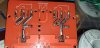
So I have a 30 amp mechanical relay that should work with my arduino or pi. I am confused as to the terminal markings. If I am reading right the leftmost pin at the top (out of each 3) is the common, the second from left being normally open with the third being normally closed.
With other relays I have used I just run power to the common, and then the switched leg from the normally open pin. This just looks odd. It threw me off that there are two middle pins that look like they are for a load as well? I just want to run 110 20 amp power to the common pin and switch it on and off
With other relays I have used I just run power to the common, and then the switched leg from the normally open pin. This just looks odd. It threw me off that there are two middle pins that look like they are for a load as well? I just want to run 110 20 amp power to the common pin and switch it on and off
Attachments
-
 2.1 MB Views: 16