stardustsailor
Well-Known Member
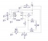
Well ,I've designed -based on some diagrams,from all over the web ,one led dimmer
for one experiment regarding led strips (SMD 5050 ) .
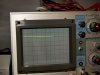
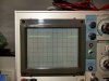
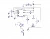
It uses a 555 timer ,as a flip-flop ,with a pot selecting the Duty Cycle .
Frequency ain't so stable,but that doesn't matter so much ,as long it remains above ~200 Hz ,
in order for the leds not to 'flicker' ....
The output signal of the 555 will open the base of a BD711 npn transistor ...
Quite good npn for this case .
It can handle 12 A continuously (Collector -emitter Current ) and peaks of 18A ...
Up to 100 Volts .With a ( Switching )transition frequency of 3MHz ...More than enough ..
( PWM frequency :300-600 Hz )
 ...
...
1) first question :The base's resistor what value should have ?
(for normal operation at 12V / 3-4 A ,and signal from 555 is ~12 Volts .Base has 5v max )
Im thinking somewhere in the range 470-1 K ....
Guod ?
Any ideas ?
2) Second question: This PWM dimmer can not be used after the output of a CC led driver ,right ?
Firstly ,because of the high voltage of the CC driver (in case of high power from leds in series )
and secondly ,because the CC driver will react ,to PWM ,trying to balance the current ..So ,I suspect serious voltage spikes ,there ...
Am I right ?
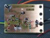
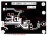
Here's the pcb ..
Most of the parts -resistors-caps-diodes - are SMD's ..
Only the 555 & the BD711 are through-hole..
(not drilled yet )
 ..
..
Guod...
Some help to an old friend ?
for one experiment regarding led strips (SMD 5050 ) .
It uses a 555 timer ,as a flip-flop ,with a pot selecting the Duty Cycle .
Frequency ain't so stable,but that doesn't matter so much ,as long it remains above ~200 Hz ,
in order for the leds not to 'flicker' ....
The output signal of the 555 will open the base of a BD711 npn transistor ...
Quite good npn for this case .
It can handle 12 A continuously (Collector -emitter Current ) and peaks of 18A ...
Up to 100 Volts .With a ( Switching )transition frequency of 3MHz ...More than enough ..
( PWM frequency :300-600 Hz )
...1) first question :The base's resistor what value should have ?
(for normal operation at 12V / 3-4 A ,and signal from 555 is ~12 Volts .Base has 5v max )
Im thinking somewhere in the range 470-1 K ....
Guod ?
Any ideas ?
2) Second question: This PWM dimmer can not be used after the output of a CC led driver ,right ?
Firstly ,because of the high voltage of the CC driver (in case of high power from leds in series )
and secondly ,because the CC driver will react ,to PWM ,trying to balance the current ..So ,I suspect serious voltage spikes ,there ...
Am I right ?
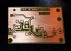
Here's the pcb ..
Most of the parts -resistors-caps-diodes - are SMD's ..
Only the 555 & the BD711 are through-hole..
(not drilled yet )
..Guod...
Some help to an old friend ?