Hi All,
I do not know a lot about electronics, just enough to tinker with Raspberry Pi's and Arduino's and make the odd circuit work.
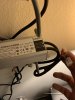
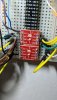
I'm very interested in trying to control the dimming feature on the HLG-480-C2100B driver I have and see that it takes a PWM signal.
I found this written on an Arduino forum:
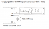
"Connect DIM- (white) to Arduino ground.
Small NPN transistor (e.g. BC547).
emitter to ground.
collector to DIM+ (blue)
1k resistor between base and one of Arduino's PWM outputs.
Write 0-255 to the PWM pin for 100-0% dimming."
Then that member posts a follow up:
"With a BC183, you must share Arduino ground with DIM(-).
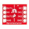
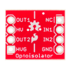
If you have an opto coupler, I would use that instead of the BC183.
The opto creates an extra layer of safety, because grounds of the two devices are NOT shared."
1) In this scenario, which device is the opto-coupler protecting? The Meanwell?, The Arduino?, or Both from one another? (If it isn't a multi-page explanation, how does not sharing a ground accomplish this?)
2) What are the dangers if I proceed using a transistor rather then an opto-coupler? (I don't care much about the arduino or raspberry pi, but don't want to fry my brand new Meanwell driver).
3) Considering how well Meanwell drivers seem to be engineered and regarded, how likely are those dangers to actually occur?
4) If the answer is that in all cases I should use an opto-coupler. I still only have a transistor in my pocket and an urge tinker right now! Would a transistor work well enough for a testbench/proof of concept? Or am I just gonna let the smoke out?
5) My understanding from the arduino forum post above is that the dimmer is inverted. This should mean if the light powers on with no PWM signal present, it would turn on at 100%. Could I hook both a potentiometer AND apply PWM at the same time? My reasoning would be that the POT would set a MAX intensity for the light should PWM fail, and then I can use PWM to further dim through automation. My reason for this would be to protect any plants not yet ready for 100% intensity in case the PWM signal fails.
6) I'd like to confirm that the dimming circuit on the meanwell can't control on/off, only dim, and that if I want to use automation to turn it on and off, it would be using a relay on the actual input power source?
Thanks for sharing your knowledge whomever might answer this!
I do not know a lot about electronics, just enough to tinker with Raspberry Pi's and Arduino's and make the odd circuit work.
I'm very interested in trying to control the dimming feature on the HLG-480-C2100B driver I have and see that it takes a PWM signal.
I found this written on an Arduino forum:
"Connect DIM- (white) to Arduino ground.
Small NPN transistor (e.g. BC547).
emitter to ground.
collector to DIM+ (blue)
1k resistor between base and one of Arduino's PWM outputs.
Write 0-255 to the PWM pin for 100-0% dimming."
Then that member posts a follow up:
"With a BC183, you must share Arduino ground with DIM(-).
If you have an opto coupler, I would use that instead of the BC183.
The opto creates an extra layer of safety, because grounds of the two devices are NOT shared."
1) In this scenario, which device is the opto-coupler protecting? The Meanwell?, The Arduino?, or Both from one another? (If it isn't a multi-page explanation, how does not sharing a ground accomplish this?)
2) What are the dangers if I proceed using a transistor rather then an opto-coupler? (I don't care much about the arduino or raspberry pi, but don't want to fry my brand new Meanwell driver).
3) Considering how well Meanwell drivers seem to be engineered and regarded, how likely are those dangers to actually occur?
4) If the answer is that in all cases I should use an opto-coupler. I still only have a transistor in my pocket and an urge tinker right now! Would a transistor work well enough for a testbench/proof of concept? Or am I just gonna let the smoke out?
5) My understanding from the arduino forum post above is that the dimmer is inverted. This should mean if the light powers on with no PWM signal present, it would turn on at 100%. Could I hook both a potentiometer AND apply PWM at the same time? My reasoning would be that the POT would set a MAX intensity for the light should PWM fail, and then I can use PWM to further dim through automation. My reason for this would be to protect any plants not yet ready for 100% intensity in case the PWM signal fails.
6) I'd like to confirm that the dimming circuit on the meanwell can't control on/off, only dim, and that if I want to use automation to turn it on and off, it would be using a relay on the actual input power source?
Thanks for sharing your knowledge whomever might answer this!