dstroy
Well-Known Member
This will be my first grow journal. I have all the parts I need to build a high pressure aeroponics indoor garden.
It will consist of at least 24 plants (not including seedlings/clones) in two 4x4 tents and a 24 site aeroponic cloner (LPA).
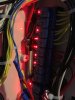
I will be using 20 (10 per tent) cxb3590 CD bin driven at 1400ma (500w/per tent) dimmed appropriately for flower/veg, and 2ft CFL for the seedlings/clones
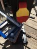
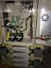
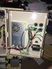
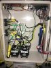
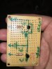
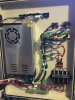
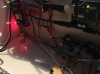
I've built myself a custom greenhouse controller out of an Arduino mega2560, some 120v contactors for the lights and everything else is controlled by regular relays.
The grow I am planning is going to be perpetual, when one tent is in flower the other will be in veg.
This is expandable by design, so if I migrate into a larger set of grow rooms all I have to do is add more pumps, accumulators, and buckets.
So far I have:
2ft 4 bulb CFL
24 site cloner
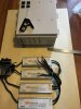
4x meanwell HLG drivers (two per fixture)
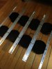
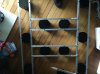
20x 140mm pin heatsinks that I drilled/tapped for ideal chip lok holders
20x cxb3590 CD bin
metal/parts to build the light fixtures (including hangers); I chose 3/4" angle aluminum 1/8" thick; the light fixtures will be 40"x40"
14000 btu aircon
72 pint dehumidifier
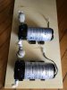
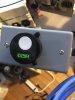
2x aquatec CDP 8800 pumps (1/4" inlet/outlet and 160psi bypass pressure)
2x 4 gallon accumulators
2x 20gal reservoirs
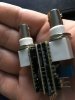
various solenoids
2x cozir CO2/temp/humidity sensors (from co2meters.com, these were expensive)
2x Arduino mega2560 (one for testing)
various relays
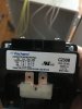
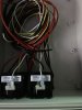
4x 120v contactors (one for each LED driver, they are high current capable and much cheaper than solid state relays)
12x 5gal food safe buckets
about 200 mister nozzles (I'll only use 2-3 per bucket; they are 3/4gph)
various fittings in 1/4" and 3/8" size to plumb the high pressure side
ph and ec meter
air pump and airstones for each reservoir
CO2 regulator with flow meter
2x co2 solenoids
What I need:
50lb CO2 bottle
seeds/clones (wife gets to choose what strains we grow)
a UPS for the pumps/Arduino in case of power loss
What I want:
a GSM shield for the Arduino so it can text me if there is a problem instead of email me but I don't want to spend the time writing the code for this
spare parts
nutes: I chose dyna gro, I've used them before to grow food and they're cheaper than cannabis specific? nutrients. and mammoth P. maybe clonex for the clones
I've got the parts, sensors and code to build PH/nute dosers.
2x kit from cyberplant on tindie
4x peristaltic pumps from amazon (12v)
2x Arduino pro mini
I'm still working on the code for these
What my controller does:
It automatically controls temperature, humidity, spray on/off time, and CO2 enrichment. All functions have hysteresis (wont turn on and off if values are close to setpoints).
Sends me an email every 5 minutes until I reply if there is a problem.
It monitors:
CO2 PPM (1500PPM setpoint nominal)
humidity
temperature
pressure of the line before the solenoid that turns on/off the misters
nute flowrate while mister is on including ramp up and down
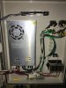
Nute flow chart:
Reservoir -> Pump -> Pressure switch -> Check valve -> Accumulator (4gal) -> Recycle solenoid -> Mister solenoid -> Misters -> Recovery
There is a separate pump/reservoir for each grow area
Why did I choose high pressure aeroponics? I believe it isn't beyond my skill level and it should be the most efficient use of space. With proper monitoring and daily logging I should be able to increase my yields. It's repeatable.
It will consist of at least 24 plants (not including seedlings/clones) in two 4x4 tents and a 24 site aeroponic cloner (LPA).
I will be using 20 (10 per tent) cxb3590 CD bin driven at 1400ma (500w/per tent) dimmed appropriately for flower/veg, and 2ft CFL for the seedlings/clones
I've built myself a custom greenhouse controller out of an Arduino mega2560, some 120v contactors for the lights and everything else is controlled by regular relays.
The grow I am planning is going to be perpetual, when one tent is in flower the other will be in veg.
This is expandable by design, so if I migrate into a larger set of grow rooms all I have to do is add more pumps, accumulators, and buckets.
So far I have:
2ft 4 bulb CFL
24 site cloner
4x meanwell HLG drivers (two per fixture)
20x 140mm pin heatsinks that I drilled/tapped for ideal chip lok holders
20x cxb3590 CD bin
metal/parts to build the light fixtures (including hangers); I chose 3/4" angle aluminum 1/8" thick; the light fixtures will be 40"x40"
14000 btu aircon
72 pint dehumidifier
2x aquatec CDP 8800 pumps (1/4" inlet/outlet and 160psi bypass pressure)
2x 4 gallon accumulators
2x 20gal reservoirs
various solenoids
2x cozir CO2/temp/humidity sensors (from co2meters.com, these were expensive)
2x Arduino mega2560 (one for testing)
various relays
4x 120v contactors (one for each LED driver, they are high current capable and much cheaper than solid state relays)
12x 5gal food safe buckets
about 200 mister nozzles (I'll only use 2-3 per bucket; they are 3/4gph)
various fittings in 1/4" and 3/8" size to plumb the high pressure side
ph and ec meter
air pump and airstones for each reservoir
CO2 regulator with flow meter
2x co2 solenoids
What I need:
50lb CO2 bottle
seeds/clones (wife gets to choose what strains we grow)
a UPS for the pumps/Arduino in case of power loss
What I want:
a GSM shield for the Arduino so it can text me if there is a problem instead of email me but I don't want to spend the time writing the code for this
spare parts
nutes: I chose dyna gro, I've used them before to grow food and they're cheaper than cannabis specific? nutrients. and mammoth P. maybe clonex for the clones
I've got the parts, sensors and code to build PH/nute dosers.
2x kit from cyberplant on tindie
4x peristaltic pumps from amazon (12v)
2x Arduino pro mini
I'm still working on the code for these
What my controller does:
It automatically controls temperature, humidity, spray on/off time, and CO2 enrichment. All functions have hysteresis (wont turn on and off if values are close to setpoints).
Sends me an email every 5 minutes until I reply if there is a problem.
It monitors:
CO2 PPM (1500PPM setpoint nominal)
humidity
temperature
pressure of the line before the solenoid that turns on/off the misters
nute flowrate while mister is on including ramp up and down
Nute flow chart:
Reservoir -> Pump -> Pressure switch -> Check valve -> Accumulator (4gal) -> Recycle solenoid -> Mister solenoid -> Misters -> Recovery
There is a separate pump/reservoir for each grow area
Why did I choose high pressure aeroponics? I believe it isn't beyond my skill level and it should be the most efficient use of space. With proper monitoring and daily logging I should be able to increase my yields. It's repeatable.